
2 layers290.1 × 130 mm

 xtech/hw-module-gps
Module for using Arduino Shield style GPS units with xBot modular platform
Hw module gps is an open-source printed circuit board by xtech, from the xtech/hw-module-gps repository on GitHub, published under the CC-BY-4.0 licence. It is a 4-layer board of 93.3 × 58 mm with 22 parts on 32 nets, routed with 47 tracks and 25 vias.
It is built around the AMS1117-3.3. Its parts include 5 ICs, 4 capacitors, 2 resistors, 1 diode and 1 connector. It belongs with the radio and wireless boards of this library.
A KiCad PCB design for a GPS module intended for the OpenMower universal mainboard. Part of the OpenMower project — open-source RTK GPS lawn mowing robotics.
| Top | Bottom |
|---|---|
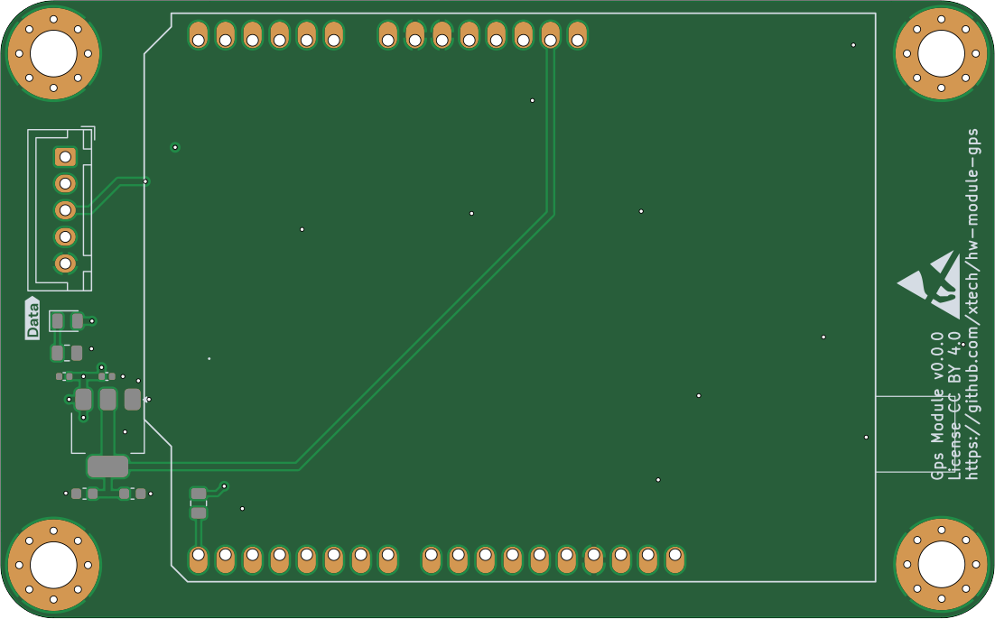 | 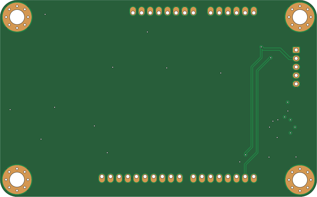 |
3D render:
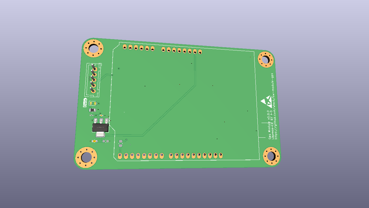
.
├── hw-module-gps.kicad_sch   # Schematic
├── hw-module-gps.kicad_pcb   # PCB layout
├── hw-module-gps.kicad_pro   # KiCad project
├── .kibot.yaml               # KiBot automation config
├── release/                  # Generated production files
│   ├── hw-module-gps-JLCPCB.zip       # Gerbers for JLCPCB
│   ├── hw-module-gps_bom_jlc.csv      # BOM (JLCPCB format)
│   ├── hw-module-gps_cpl_jlc.csv      # Pick-and-place (JLCPCB format)
│   ├── hw-module-gps-schematic.pdf    # Schematic PDF
│   └── hw-module-gps-ibom.html        # Interactive BOM
├── 3d/                       # Custom 3D models
├── xcore-lib/                # Custom symbol library
└── logos/ # SVG assets used on PCB silkscreenAll production files are pre-generated in release/:
release/hw-module-gps-JLCPCB.zip as gerbersrelease/hw-module-gps_bom_jlc.csv as BOMrelease/hw-module-gps_cpl_jlc.csv as CPLrelease/hw-module-gps-ibom.html (open in browser) to verify component placementRequires Docker.
./run-kibot-docker.shThis runs KiBot via ghcr.io/inti-cmnb/kicad9_auto:1.8.5 and regenerates all files in release/.
Requires KiCad 9. Open hw-module-gps.kicad_pro.
Before building a robot using these designs, verify that doing so is permitted in your jurisdiction. Patents and local regulations may apply.
The files are distributed without any warranty — no guarantee of safety, legality, or correct function. You need the technical knowledge to evaluate and use this design. The author is not liable for any damages.

Licensed under Creative Commons Attribution 4.0 International.
| Qty | Value | Footprint | References |
|---|---|---|---|
| 4 | MountingHole_Pad | MountingHole:MountingHole_4.3mm_M4_Pad_Via | H5, H6, H10, H15 |
| 2 | 2.54mm 1x8 socket | xtech:Dummy | U43, U44 |
| 2 | 22uF | Capacitor_SMD:C_0603_1608Metric | C119, C120 |
| 2 | G*** | kibuzzard-69B58D65 | kibuzzard-69B58D65, kibuzzard-69B58D65 |
| 1 | 100nF | Capacitor_SMD:C_0402_1005Metric | C63 |
| 1 | 10uF | Capacitor_SMD:C_0402_1005Metric | C37 |
| 1 | 1k | Resistor_SMD:R_0805_2012Metric | R44 |
| 1 | 2.2k | Resistor_SMD:R_0805_2012Metric | R59 |
| 1 | 2.54mm 1x10 socket | xtech:Dummy | U45 |
| 1 | 2.54mm 1x6 socket | xtech:Dummy | U42 |
| 1 | AMS1117-3.3 | Package_TO_SOT_SMD:SOT-223-3_TabPin2 | U12 |
| 1 | Ardusimple_F9P | xtech:Arduino_Uno_Shield_Ardusimple_Budget | XA1 |
| 1 | Conn_01x05 | Connector_JST:JST_XH_B5B-XH-A_1x05_P2.50mm_Vertical | J29 |
| 1 | ESD-Logo_6.6x6mm_SilkScreen | Symbol:ESD-Logo_6.6x6mm_SilkScreen | LOGO2 |
| 1 | G*** | kibuzzard-67111AE1 | kibuzzard-67111AE1 |
| 1 | LED GREEN | LED_SMD:LED_0805_2012Metric | D25 |
It measures 93.3 × 58 mm and has 4 copper layers, 1.6 mm thick.
22 parts, built around the AMS1117-3.3. The full list of its parts is on this page, with links to each part's symbol and footprint where PCBKit's library has them.
From the xtech/hw-module-gps repository on GitHub, at the commit this page was made from: the board is hw-module-gps.kicad_pcb and its schematic hw-module-gps.kicad_sch. PCBKit opens the board in the browser, with nothing to install.
Its repository publishes it under the CC-BY-4.0 licence: you may reuse it on that licence's terms (keep the author's notice, and for a copyleft licence share your changes alike).

pascallanger/DIY-Multiprotocol-TX-Module
Multiprotocol TX Module (or MULTI-Module) is a 2.4GHz transmitter module which controls many different receivers and models.

fossasia/pslab-hardware
PSLab Hardware Design and Schematics https://pslab.io


MaltWhiskey/Mega-Cube
16x16x16 PL9823 Cube with Teensy 4.0 and FlexIO driver


shamansystems/Cheap-FOCer-2
Low-Cost Motor Controller based on the VESC 6