2 layers140 × 45 mm
 xdylanm/gate-delay
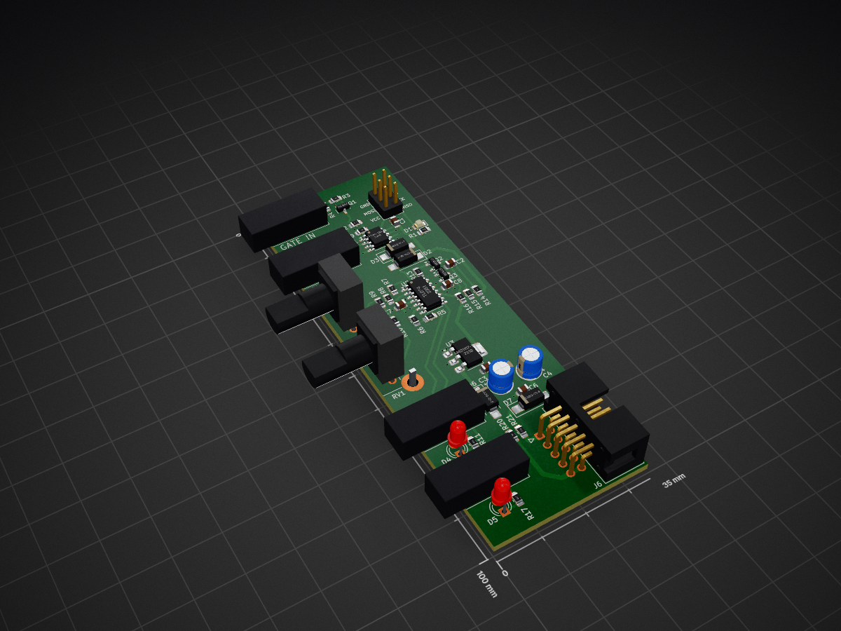
Gate delay module for Eurorack
Ic gate delay is an open-source printed circuit board by xdylanm, from the xdylanm/gate-delay repository on GitHub, published under the MIT licence. It is a 4-layer board of 35 × 100 mm with 50 parts on 38 nets, routed with 229 tracks and 28 vias.
It is built around the ATTINY13A-SU, AMS1117-5.0 and B140Q-13-F-HXY, with the BC847 among its other parts. Its parts include 21 resistors, 8 capacitors, 7 diodes, 6 connectors and 3 ICs. It belongs with the audio and music boards and the AVR (ATmega, ATtiny) boards of this library.


A gate delay module in the Eurorack format. The module is implemented with an ATTiny13a microcontroller, with features including
A second, fully analog design is also described. This design is based on a current mirror and integration capacitor, and also maintains the gate pulse length. I have not implemented and tested this one.
| Qty | Value | Footprint | References |
|---|---|---|---|
| 7 | 100k | Resistor_SMD:R_0805_2012Metric_Pad1.20x1.40mm_HandSolder | R3, R4, R6, R7, R8, R9, R10 |
| 5 | 100n | Capacitor_SMD:C_0805_2012Metric | C1, C5, C6, C7, C8 |
| 5 | 10k | Resistor_SMD:R_0805_2012Metric_Pad1.20x1.40mm_HandSolder | R2, R13, R14, R16, R19 |
| 4 | B140Q-13-F | Diode_SMD:D_SMA_Handsoldering | D2, D3, D6, D7 |
| 4 | MonoJack | AudioJacks:Jack_3.5mm_QingPu_WQP-PJ323M_Horizontal | J1, J2, J3, J4 |
| 3 | 1k | Resistor_SMD:R_0805_2012Metric_Pad1.20x1.40mm_HandSolder | R5, R12, R18 |
| 3 | 4k7 | Resistor_SMD:R_0805_2012Metric_Pad1.20x1.40mm_HandSolder | R1, R11, R17 |
| 3 | BC847 | Package_TO_SOT_SMD:SOT-23 | Q1, Q2, Q3 |
| 2 | 100k | Potentiometer_THT:Potentiometer_Bourns_PTV09A-2_Single_Horizontal | RV1, RV2 |
| 2 | 10R | Resistor_SMD:R_0805_2012Metric_Pad1.20x1.40mm_HandSolder | R20, R21 |
| 2 | 10u | Capacitor_THT:CP_Radial_D5.0mm_P2.50mm | C3, C4 |
| 2 | LED | LED_THT:LED_D3.0mm | D4, D5 |
| 1 | 10n | Capacitor_SMD:C_0805_2012Metric | C2 |
| 1 | 150k | Resistor_SMD:R_0805_2012Metric_Pad1.20x1.40mm_HandSolder | R15 |
| 1 | AMS1117-5.0 | Package_TO_SOT_SMD:SOT-223-3_TabPin2 | U3 |
| 1 | ATtiny13A-S | Package_SO:SOIC-8_3.9x4.9mm_P1.27mm | U1 |
| 1 | Conn_02x03_Odd_Even | Connector_PinHeader_2.54mm:PinHeader_2x03_P2.54mm_Vertical | J5 |
| 1 | Conn_02x05_Odd_Even | Connector_IDC:IDC-Header_2x05_P2.54mm_Horizontal | J6 |
| 1 | LED | LED_SMD:LED_0805_2012Metric_Pad1.15x1.40mm_HandSolder | D1 |
| 1 | TL074 | Package_SO:SOIC-14_3.9x8.7mm_P1.27mm | U2 |
It measures 35 × 100 mm and has 4 copper layers, 1.6 mm thick.
50 parts, built around the ATTINY13A-SU, AMS1117-5.0, B140Q-13-F-HXY and BC847. The full list of its parts is on this page, with links to each part's symbol and footprint where PCBKit's library has them.
From the xdylanm/gate-delay repository on GitHub, at the commit this page was made from: the board is hardware/ic-gate-delay/ic-gate-delay.kicad_pcb and its schematic hardware/dual-gate-delay-faceplate/dual-gate-delay-faceplate.kicad_sch. PCBKit opens the board in the browser, with nothing to install.
Its repository publishes it under the MIT licence: you may reuse it on that licence's terms (keep the author's notice, and for a copyleft licence share your changes alike).


shm-dmitry/auto_close_window
This IOT project allows you to open and close your window from any smart house. For example - you can setup rules like a "If night and noise greater then expected -> close window" and "Noise reduced -> open window"

ZoidTechnology/PCIce
A PCI Express card with an inbuilt PWM fan controller and mounting points for an 80mm fan.


MouseBiteLabs/NES-Cartridges
A collection of Nintendo Entertainment System (NES) cartridge circuit boards