

2 layers180.1 × 180.3 mm
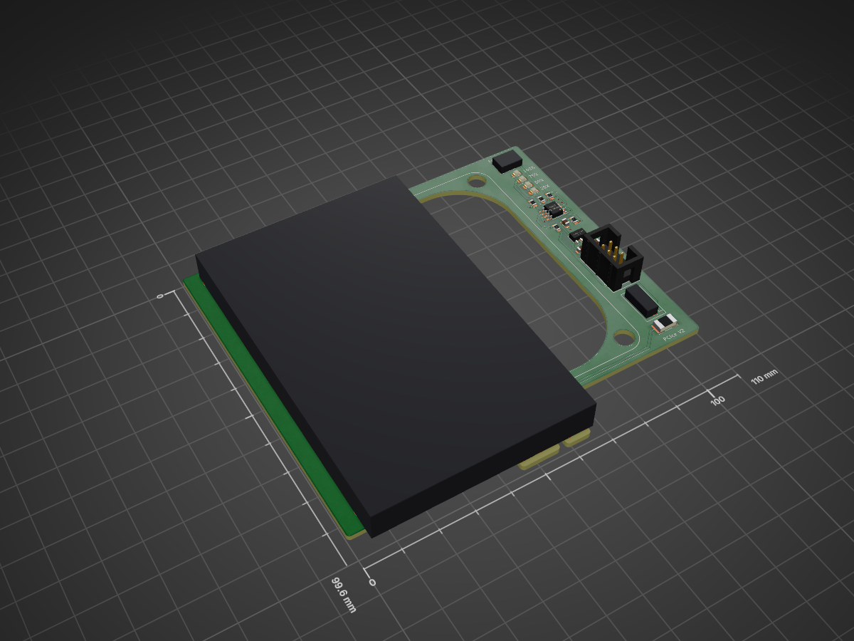
A PCI Express card with an inbuilt PWM fan controller and mounting points for an 80mm fan.
PCIce is an open-source printed circuit board by ZoidTechnology, from the ZoidTechnology/PCIce repository on GitHub, published under the GPL-3.0 licence. It is a 2-layer board of 110 × 99.6 mm with 22 parts on 15 nets, routed with 132 tracks and 23 vias.
It is built around the ATTINY13A-SU. Its parts include 5 resistors, 4 diodes, 3 capacitors, 3 connectors and 2 ICs. It belongs with the computers and single-board computers boards and the AVR (ATmega, ATtiny) boards of this library.
A PCI Express card with an inbuilt PWM fan controller and mounting points for an 80mm fan.
PCIce is available to buy on Tindie.
More information can be found on my website.
The hardware is based on an ATtiny13A which outputs a 25kHz PWM signal to the fan. A button is used for speed control, and the current speed is displayed on four multiplexed LEDs.
The firmware attempts to load the speed setting from EEPROM on boot. The speed setting is stored twice to guard against corruption. The second copy is inverted to detect a blank EEPROM. The speed will default to maximum if corruption is detected to prevent overheating. The button is debounced in software and must be released for a short period before the next press is registered.
The firmware can be compiled and flashed with the build script inside the firmware directory. This script expects an AVRISP MKII to be connected over USB. avr-gcc, avr-objcopy, avrdude and avr-libc are required to build the firmware.
PCIce is licensed under the GNU GPLv3 license. This license does not cover the use of Zoid Technology trademarks. A list of trademarks can be found here.
| Qty | Value | Footprint | References |
|---|---|---|---|
| 4 | 4K7 | _Footprints:R_0805 | R2, R3, R4, R5 |
| 4 | LED | _Footprints:LED_0805 | D1, D2, D3, D4 |
| 2 | 1U | _Footprints:C_0805 | C1, C2 |
| 1 | 100N | _Footprints:C_0805 | C3 |
| 1 | 1A | _Footprints:F_1812 | F1 |
| 1 | 220 | _Footprints:R_0805 | R1 |
| 1 | 5V SOT-89 REG | _Footprints:SOT89-3 | U1 |
| 1 | ATTINY13A | _Footprints:SOIC-8 | U2 |
| 1 | CON 2X3 | _Footprints:GENERIC_IDC_2X3 | J1 |
| 1 | CON 3+1 | _Footprints:744-81-04TB1B | J2 |
| 1 | LPTS | _Footprints:GENERIC_LOW_PROFILE_SWITCH | SW1 |
| 1 | PCIE X1 12V | _Footprints:PCIE_X1_12V | J3 |
The 19 most common of 22 parts.
It measures 110 × 99.6 mm and has 2 copper layers, 1.6 mm thick.
22 parts, built around the ATTINY13A-SU. The full list of its parts is on this page, with links to each part's symbol and footprint where PCBKit's library has them.
From the ZoidTechnology/PCIce repository on GitHub, at the commit this page was made from: the board is hardware/pcice.kicad_pcb and its schematic hardware/pcice.kicad_sch. PCBKit opens the board in the browser, with nothing to install.
Its repository publishes it under the GPL-3.0 licence: you may reuse it on that licence's terms (keep the author's notice, and for a copyleft licence share your changes alike).

MouseBiteLabs/NES-Cartridges
A collection of Nintendo Entertainment System (NES) cartridge circuit boards

MakersFunDuck/Common-Kitchen-Timer-With-LCD-Replacement-Board
A replacement PCB board for common 4 digit 7 segment LCD kitchen timers.

AR1972/Xbox_tray_emulator
Original Xbox DVD tray emulation via ATtiny MCU


leandroebner/Morse-Code-LED-Blinker
Designed for educational use, this minimalistic LED-based project offers an accessible and effective platform for learning the fundamentals of soldering, electronics, and programming.