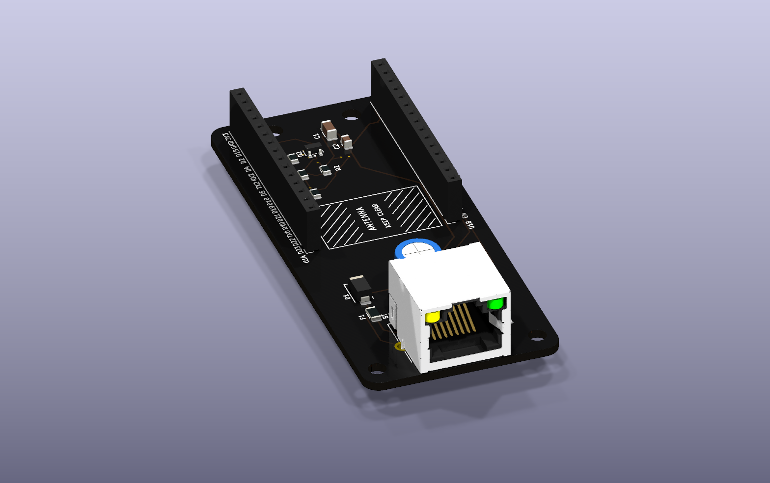
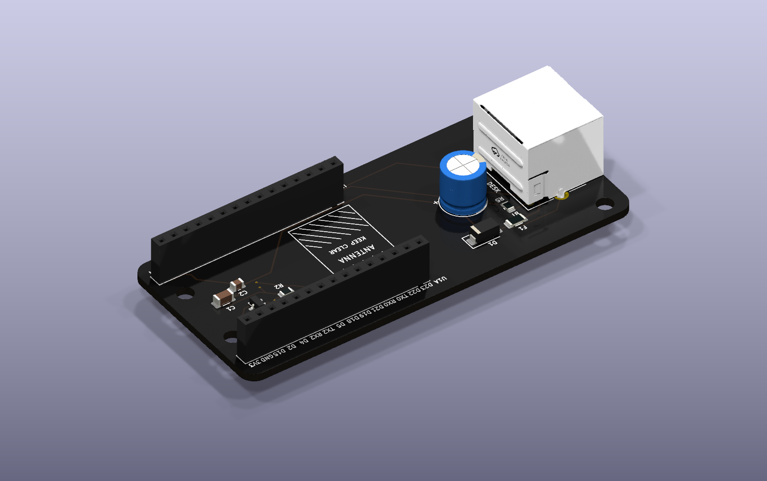
Desk companion board
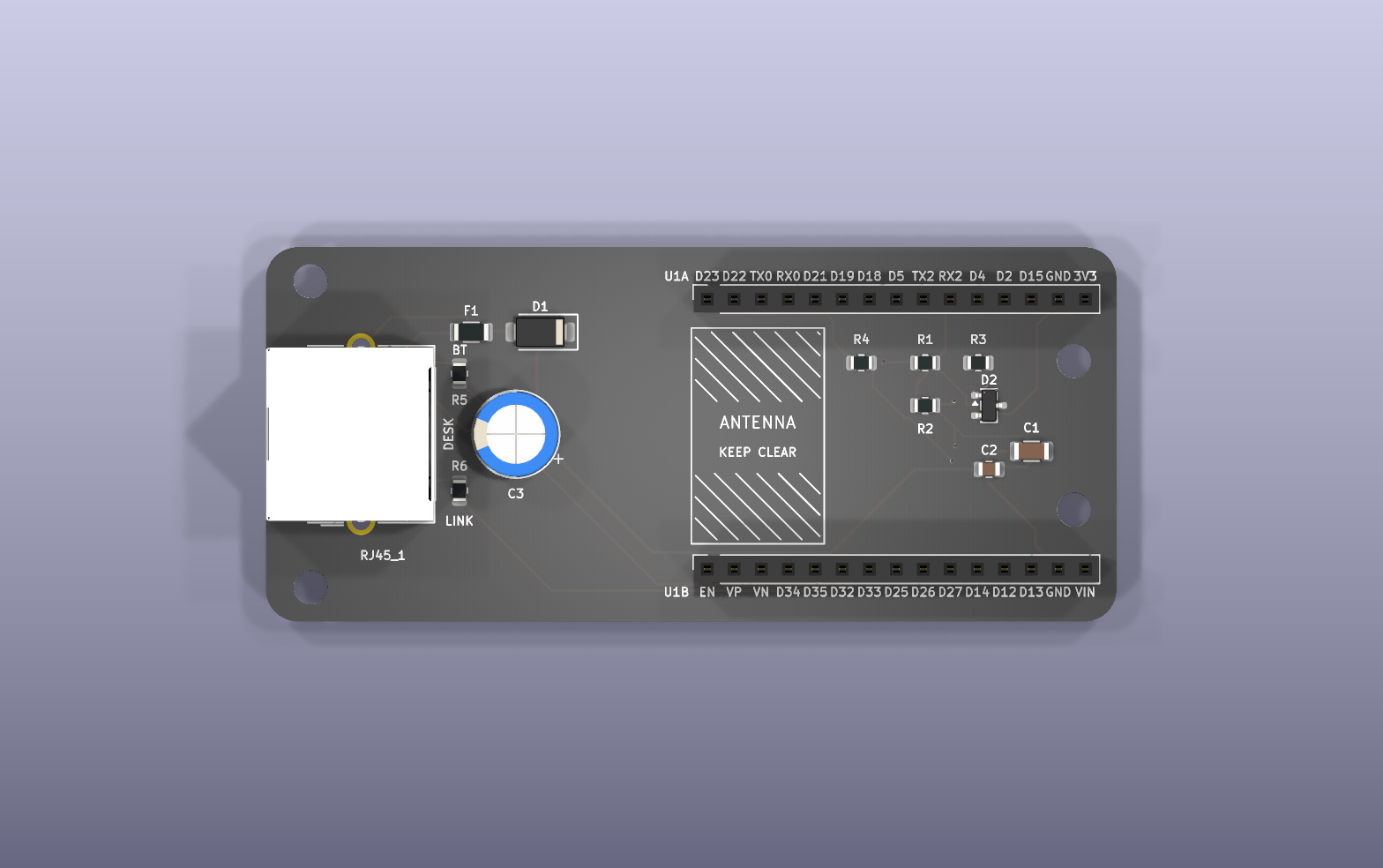
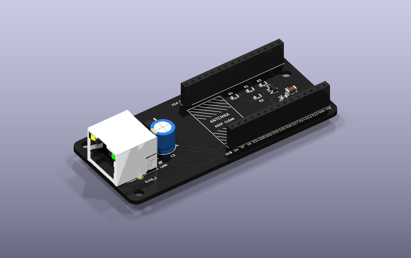
A carrier for an ESP32 DevKit V1 (30-pin) that plugs into a LoctekMotion / Flexispot control box over RJ45. It runs off the desk's 5 V, shifts the box's 5 V signal down for the ESP32, and uses the jack's two LEDs for Bluetooth (BT) and the desk link (LINK). What they show is in getting started. The firmware is in ../proxy.
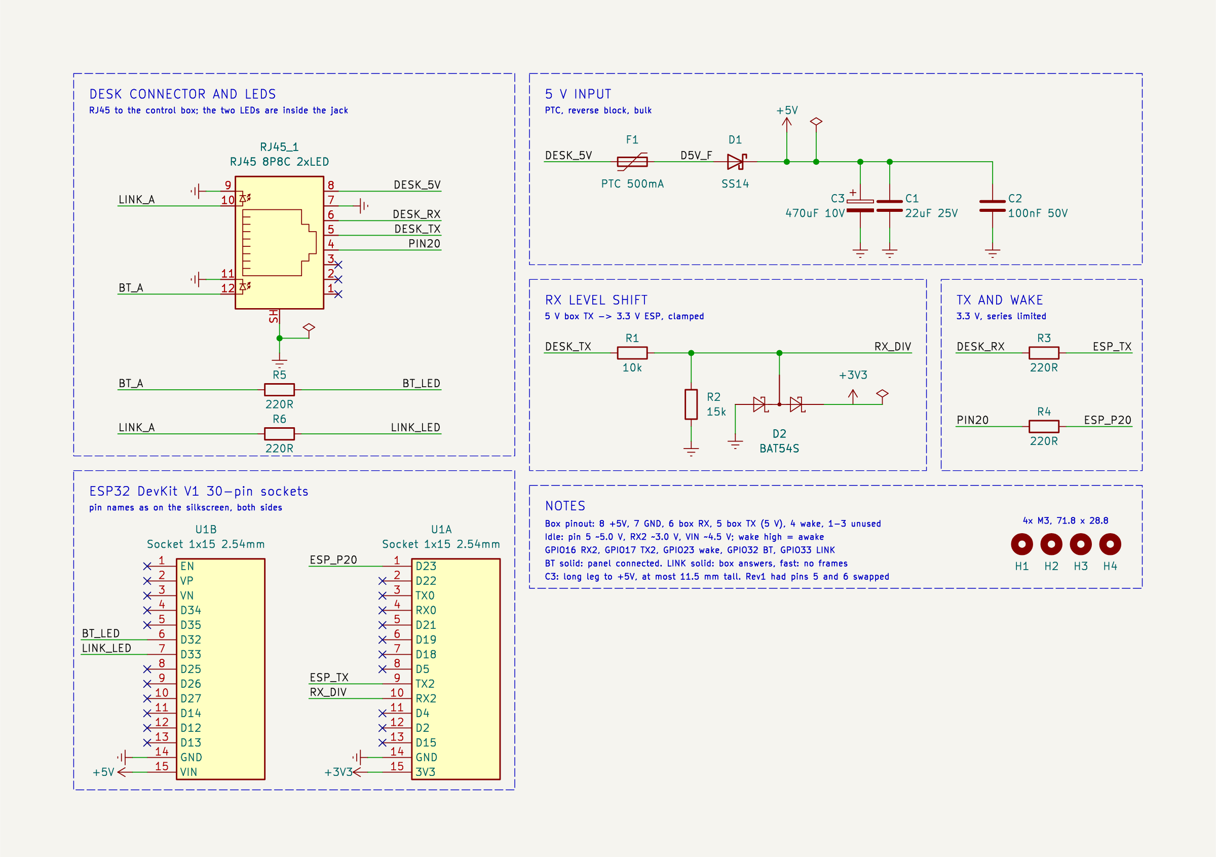
Rev2, 80 × 35.2 mm, two layers, 4 × M3. The schematic is also a PDF.
Wiring
| RJ45 pin | Control box | On the board | ESP32 |
|---|
| 8 | 5 V | PTC fuse, SS14 diode, 470 µF | VIN |
| 7 | GND | ground pour | GND |
| 6 | box RX | 220 Ω | GPIO17 (TX2) |
| 5 | box TX, 5 V | 10k / 15k divider, BAT54S clamp | GPIO16 (RX2) |
| 4 | wake ("PIN 20") | 220 Ω | GPIO23 |
| 12 / 11 | LED | 220 Ω | GPIO32, BT |
| 10 / 9 | LED | 220 Ω | GPIO33, LINK |
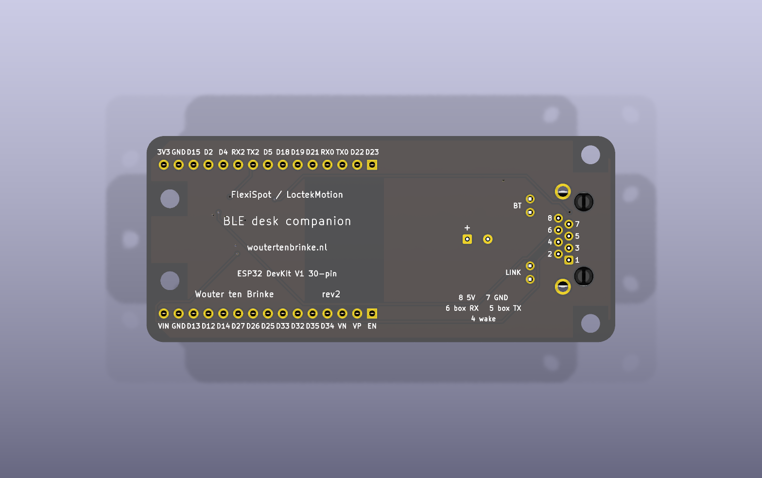
This is how my control box uses pins 4 to 8: it sends on pin 5 and listens on pin 6, as the published LoctekMotion tables have it. Measure yours before plugging it in. The back of the board names what you probe there: the jack's pin numbers beside its pads with what each carries, BT and LINK by the LED pads, C3's + side, and the DevKit's pin names along both sockets, as on the top.
The companion firmware's defaults are this board's: TX on GPIO17, RX on GPIO16, wake on GPIO23.
Ordering
Upload fab/tab5-desk-ctrl-gerbers.zip, -bom.csv and -cpl.csv to JLCPCB with SMT assembly on the top side. The jack, the two headers and C3 are hand-soldered, see fab/tab5-desk-ctrl-hand-solder.csv. Print fab/tab5-desk-ctrl-check-1to1.pdf at 100 % and hold the jack and the DevKit against it before you order.
Files
The KiCad files are generated by the Python scripts here, so change the scripts rather than the board. make_fab.sh builds everything in fab/, and render.sh the pictures in img/. The scripts look for KiCad 9 where macOS puts it; KICAD9_FOOTPRINT_DIR, KICAD9_SYMBOL_DIR and KICAD_CLI point them elsewhere. The jack is LCSC part C386757, where its datasheet is; its 3D model in 3dmodels/ is LCSC's.
Things to know
- Only for a box with 5 V on pin 8. Nothing on the board protects against more: a LoctekMotion variant with about 29 V there destroys the capacitors, the DevKit's regulator and probably the ESP32.
- C3 has a + side. It is the 470 µF electrolytic behind the jack, 10 V or more, 8 mm across and no taller than 11.5 mm, its long leg in the pad marked +. It is optional: the companion also starts without it, with one restart at power-up. It carries the radio's start-up surge: on desk power alone, rev1 browned out and restarted at every boot.
- Rev1 had pins 5 and 6 the other way round. On a rev1 board the companion needs TX on GPIO16 and RX on GPIO17, in
proxy/sdkconfig, and R1 bridged, since commands to the box cannot pass its 10k. GPIO17 then takes the box's 5 V through 220 Ω, which is outside the ESP32's ratings.
- The diode has to be a BAT54S. The BAT54A and BAT54C come in the same package and both break RX without a sound: one holds the line near 0.6 V, the other keeps its low near 2.7 V. With the box idle, GPIO16 should read about 3.1 V.
- Use flux made for electronics. Acid flux for plumbing, such as S-39, leaves a residue that conducts: on a rev1 board it leaked about 6 kΩ from pin 6 to ground and held the box's signal down.
- R2 is 15k. The box's TX measured between 5.01 and 5.17 V; 10k over 15k puts that at 3.0 to 3.1 V, inside the ESP32's 3.3 V with room either side, whichever of those it is.
- Pick the soldermask, silkscreen and finish on the order form. JLCPCB does not read them from the files.
- The LED polarity is from the jack's datasheet, not measured. A LED that stays dark is the wrong way round, which does it no harm. At start-up the companion blinks
BT twice, LINK twice, then both.