
2 layers67.3 × 74.9 mm

 wsprtv/vagabond11
Vagabond1 WSPR Transmitter
Vagabond1 is an open-source printed circuit board by wsprtv, from the wsprtv/vagabond1 repository on GitHub. It is a 2-layer board of 15.2 × 22.2 mm with 21 parts on 28 nets, routed with 123 tracks and 25 vias.
It is built around the SI5351A-B-GT. Its parts include 8 capacitors, 6 connectors, 3 resistors, 3 ICs and 1 crystal.
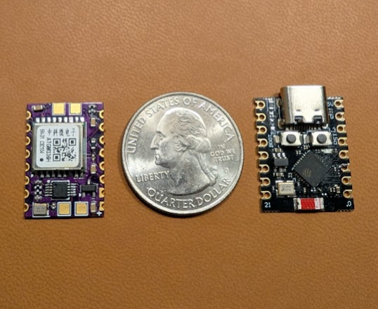
Vagabond1 is a tiny WSPR transmitter that piggybacks on the popular ESP32 C3 Super Mini board. It contains only 11 components (including 7 passives). Vagabond1 is fully supported by Nomad firmware.
Vagabond1 boards can be assembled at JLCPCB using these fabrication files. An alternative BOM is provided replacing MS5351m with Si5351a. While the two parts have nearly identical performance, Si5351a consumes less power.
Select 0.8mm board thickness.
When soldering Vagabond1 and ESP32 C3 Super Mini boards together, orient them so that the GPS module is away from the USB-C port.
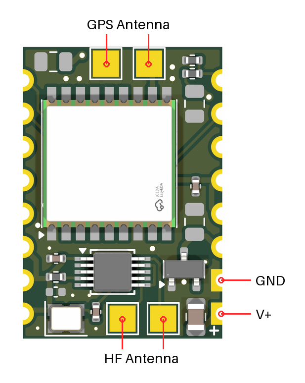
The recommended GPS antenna is a magnetic wire (~30AWG) dipole with a ~30mm twisted feedline and ~46mm legs.
A 3D-printable frame is available for mounting Vagabond1 boards to six 52x19 or 39x19 solar cells.
The ESP32 board needs two modifications when powered with solar cells.
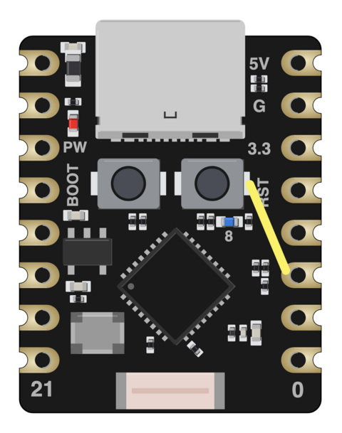
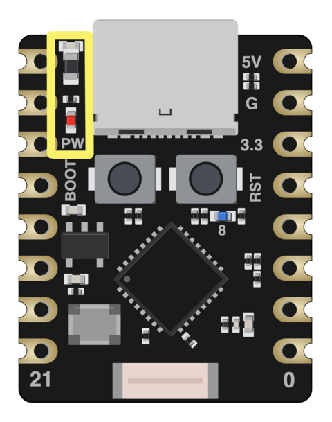
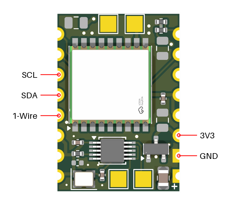
Your I2C sensor should have a 4.7k or 10k pullup resistor on SCL. A pullup resistor on SDA is optional. In Nomad CT handlers, initialize I2C as follows:
from machine import I2C, Pin
i2c = I2C(0, scl = Pin(10), sda = Pin(9), freq = 100000)
For 1-Wire protocols (such as DS18B20 temperature sensors), use pin 8 for the data line. This pin is shared with the blue LED, so disable the LED in settings to avoid interference. More than one sensor may be attached to the same data line, and no pullup resistor is needed.
All mesurements were performed with a 3.6V power supply.
50 ohm levels were measured with a tinySA Ultra+ spectrum analyzer and may have up to 2 dB of absolute error. 75 ohm levels were derived from peak-to-peak voltages measured across a 75 ohm resistor with a high-bandwidth oscilloscope.
| State | Current (mA) |
|---|---|
| Idle, enable_lp_sleep = False | 7 |
| Idle, enable_lp_sleep = True | 0.3 |
| GPS Acquisition | 30-32 |
| Red LED On | 0.3 |
| Blue LED On | 0.5 |
| Nomad TX Power | Current (mA) | Output Power (dBm) |
|---|---|---|
| Low (LP) | 47 | 5.3 |
| Medium (MP) | 52 | 9.0 |
| High (HP) | 65 | 13.7 |
| Ultra-High (UHP) | 69 | 15.4 |
| Nomad TX Power | Current (mA) | Output Power (dBm) |
|---|---|---|
| Low (LP) | 32 | 4.4 |
| Medium (MP) | 39 | 8.9 |
| High (HP) | 53 | 14.2 |
| Ultra-High (UHP) | 55 | 15.3 |
| Nomad TX Power | Current (mA) | Output Power (dBm) |
|---|---|---|
| Low (LP) | 46 | 7.1 |
| Medium (MP) | 50 | 10.0 |
| High (HP) | 63 | 14.3 |
| Ultra-High (UHP) | 66 | 15.8 |
| Nomad TX Power | Current (mA) | Output Power (dBm) |
|---|---|---|
| Low (LP) | 32 | 6.1 |
| Medium (MP) | 38 | 10.3 |
| High (HP) | 51 | 15.1 |
| Ultra-High (UHP) | 53 | 16.0 |
| Qty | Value | Footprint | References |
|---|---|---|---|
| 4 | 47u | Capacitor_SMD:C_0805_2012Metric | C1, C3, C4, C5 |
| 4 | Conn_01x01_Pin | TestPoint:TestPoint_Pad_2.0x2.0mm | J1, J2, J5, J6 |
| 2 | 100n | Capacitor_SMD:C_0402_1005Metric | C6, C8 |
| 2 | 10k | Resistor_SMD:R_0402_1005Metric | R1, R3 |
| 2 | 10u | Capacitor_SMD:C_0402_1005Metric | C2, C7 |
| 2 | Conn_01x08_Pin | Connector_PinHeader_2.54mm:PinHeader_1x08_P2.54mm_Vertical | J3, J4 |
| 1 | 47k | Resistor_SMD:R_0402_1005Metric | R2 |
| 1 | ATGM336H | vagabond1:ATGM336H | U1 |
| 1 | Si5351A-B-GT | Package_SO:MSOP-10_3x3mm_P0.5mm | U3 |
| 1 | TCXO | vagabond1:TCXO_4Pin_2.5x2.0mm | X1 |
| 1 | V-MONITOR | Package_TO_SOT_SMD:SOT-23 | U2 |


DRWJSCHMIDT/T41
This is the repository for the officially released V10, V11, and V12 versions of the T41 Software Defined Transceiver hardware and kits.

AidanHockey5/MegaBlaster2
The latest iteration of my hardware Sega Genesis/Megadrive Video Game Music Player

MouseBiteLabs/Super-Game-Boy-Plus
A replacement circuit board for improving the Super Game Boy, or for creating a standalone Game Boy game for the SNES.

kholia/Si5351-Module-Clone-TCXO
Si5351-Module-Clone with low PPM TCXO! Drop-in replacement for the Adafruit's Si5351 module. 3.3v ONLY!

It measures 15.2 × 22.2 mm and has 2 copper layers, 0.8 mm thick.
21 parts, built around the SI5351A-B-GT. The full list of its parts is on this page, with links to each part's symbol and footprint where PCBKit's library has them.
From the wsprtv/vagabond1 repository on GitHub, at the commit this page was made from: the board is kicad/vagabond1.kicad_pcb and its schematic kicad/vagabond1.kicad_sch. PCBKit opens the board in the browser, with nothing to install.
Its repository states no licence, so its author keeps all rights: ask wsprtv before reusing the design.