
2 layers68.8 × 53.6 mm
Relatively Universal ROM Programmer
AndersBNielsen/Relatively-Universal-ROM-Programmer
Hardware to program W27C512 EEPROM or any 24/28/32 pin ROM requiring from 5V to 27V programming voltage.
149 parts257GPL-3.0
 wrightedu/mood
Ahem, I mean welcome to the PCB design portion of your summer camp!
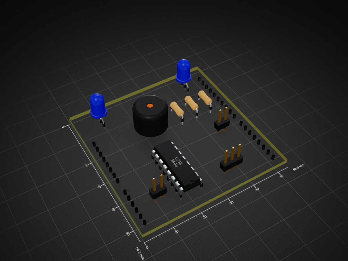
Updated mood is an open-source printed circuit board by wrightedu, from the wrightedu/mood repository on GitHub. It is a 2-layer board of 53.9 × 54.2 mm with 11 parts on 41 nets, routed with 42 tracks and 0 vias.
It is built around the ARDUINO UNO R3. Its parts include 3 resistors, 3 connectors, 2 diodes and 1 IC. It belongs with the AVR (ATmega, ATtiny) boards of this library.

Welcome to you're doom!
Ahem, I mean welcome to the PCB design portion of your summer camp!
This project was selected to introduce a variety of topics including:
By the end of these two weeks you will have a basic understanding of how to layout and build a basic circuit and what vulnerabilities it may have (unintentional or otherwise).
A (brief) word on safety. All of the equipment and materials used in this project are safe, so long as they are used properly.
Our goal is to make sure that over the two weeks of this project you are instructed on how to perform each of the steps needed to manufacture a PCB safely. Please do NOT turn on any of the machines or use any of the equipment until you have had the safety overview for that equipment or process.
Similarly, if you are unsure on the safe way to perform some process just ask one of
our several lab assistants. We are happy to help! There will be additional safety
instructions covered over the course of the two weeks and all relevant safety documents
will be kept in the Safety folder in this repository.
Most of the materials have already been inlcuded in your Elegoo kit. These include:
Other items needed include:
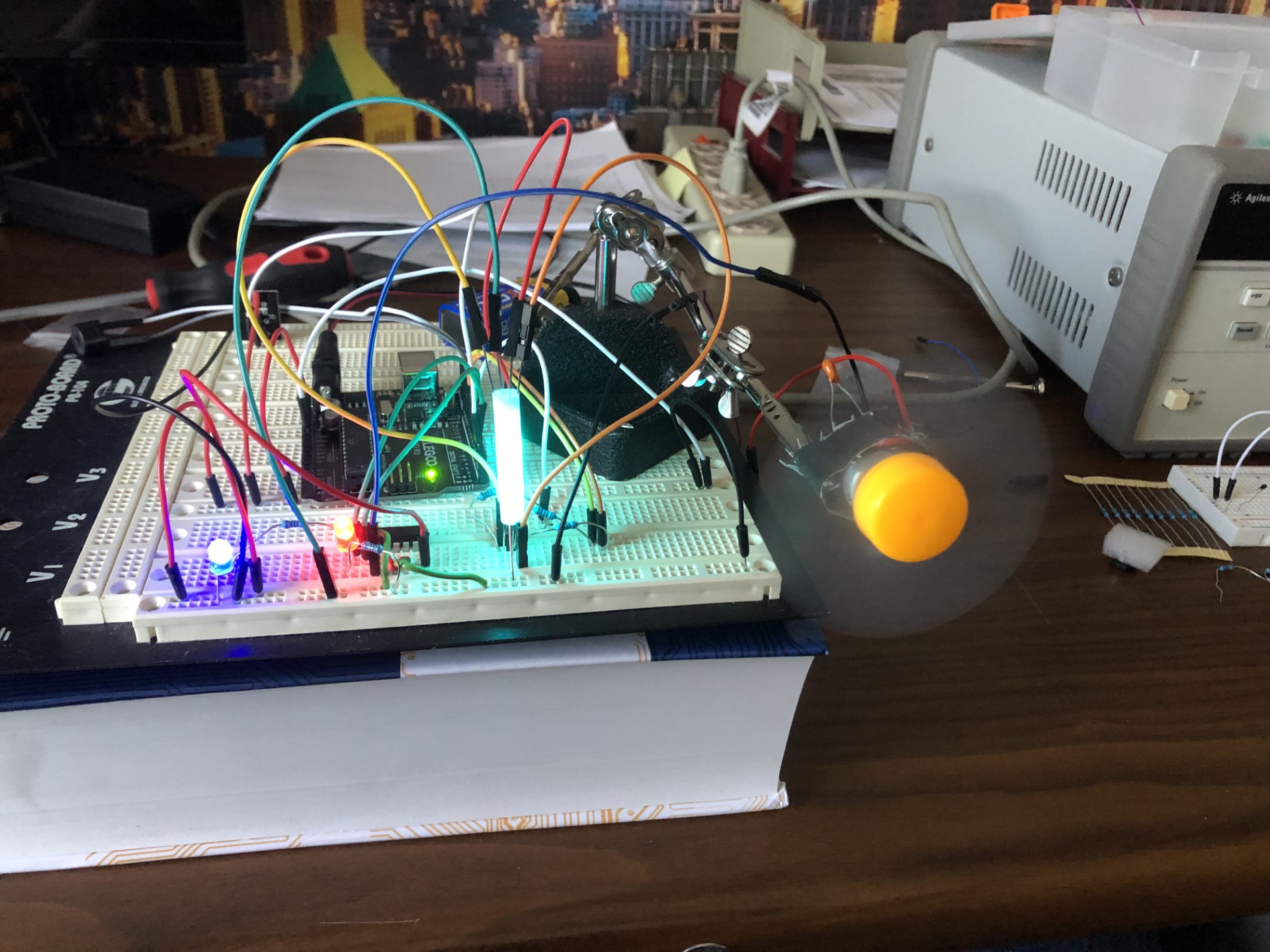
The circuit started as this:
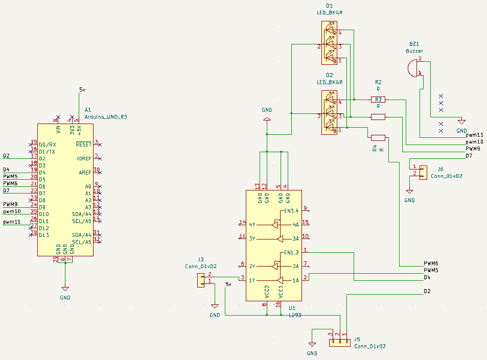
This is the schematic:
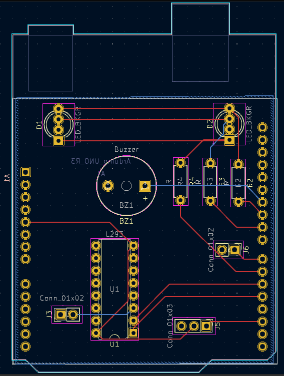
This is the PCB layout:
This is the final product:
We will be using the open source Computer-Aided Drawing / Electronics Design Automation (CAD/EDA) suite KiCad. This software can be installed freely on Windows/Mac/Linuxand is very powerful. Further documentation and cheatsheets can be found in the KiCad folder of this repository.
The project aims to design a remote-controlled color-changing light system with RGB LEDs controlled by three PWM signals. The system will be operated using an IR remote controller, allowing users to adjust LED colors and brightness levels to create various vibrant RGB combinations. Notably, as a part of the project's educational goals, an intentional inclusion of "malicious" code will be introduced. This demonstration will emphasize the importance of secure coding practices, as the code will play the E1M1 DOOM song when a specific button sequence is entered. The project's primary focus is on exploring LED control technology, color customization, and the implications of unsecured coding practices. Safety measures will not be implemented, as the project's central objective is to highlight the potential risks associated with inadequate security measures. The project seeks to provide users with an informative and insightful experience while demonstrating the significance of security in electronic systems.
| Qty | Value | Footprint | References |
|---|---|---|---|
| 3 | R | Resistor_THT:R_Axial_DIN0207_L6.3mm_D2.5mm_P7.62mm_Horizontal | R2, R3, R4 |
| 2 | Conn_01x02 | Connector_PinHeader_2.54mm:PinHeader_1x02_P2.54mm_Vertical | J3, J6 |
| 2 | LED_BKGR | LED_THT:LED_D5.0mm-4_RGB_Wide_Pins | D1, D2 |
| 1 | Arduino_UNO_R3 | Module:Arduino_UNO_R3 | A1 |
| 1 | Buzzer | Buzzer_Beeper:Buzzer_12x9.5RM7.6 | BZ1 |
| 1 | Conn_01x03 | Connector_PinHeader_2.54mm:PinHeader_1x03_P2.54mm_Vertical | J5 |
| 1 | L293 | Package_DIP:DIP-16_W7.62mm | U1 |
It measures 53.9 × 54.2 mm and has 2 copper layers, 1.6 mm thick.
11 parts, built around the ARDUINO UNO R3. The full list of its parts is on this page, with links to each part's symbol and footprint where PCBKit's library has them.
From the wrightedu/mood repository on GitHub, at the commit this page was made from: the board is updated_mood/updated_mood.kicad_pcb and its schematic KiCad/updated_mood.kicad_sch. PCBKit opens the board in the browser, with nothing to install.
Its repository states no licence, so its author keeps all rights: ask wrightedu before reusing the design.
AndersBNielsen/Relatively-Universal-ROM-Programmer
Hardware to program W27C512 EEPROM or any 24/28/32 pin ROM requiring from 5V to 27V programming voltage.

AlanFord/self-balancing-stick
Dual Axis Reaction Wheel Inverted Pendulum

Edging-Machines/Edging-Machines
This repository is intended to contain as much information as possible about building, designing, prototyping, and using automated edging machines.

PedroCNeves/AC_ChargingStation
A learning project to create an EV AC Charging station based on an Arduino Uno

jonsag/arduTester
An arduino component tester based on https://create.arduino.cc/projecthub/plouc68000/ardutester-v1-13-the-arduino-uno-transistor-tester-dbafb4


ICRS/101
The all-new open source Robotics 101 course from ICRS. It's specifically designed to be run in hackspaces, after school clubs and university societies.
