4 layers164 × 118 mm
OpenEFI rev4 bkp
Churrosoft/OpenEFI-PCB
Coleccion de PCB y planos recomendados para montar una OpenEFI
345 parts8CERN-OHL-S-2.0

 wolffshots/esp-ip
This project is a hardware solution that leverages the power of the ESP32 to bridge local communication interfaces, such as serial and (in the future) I2C, to a WiFi network.
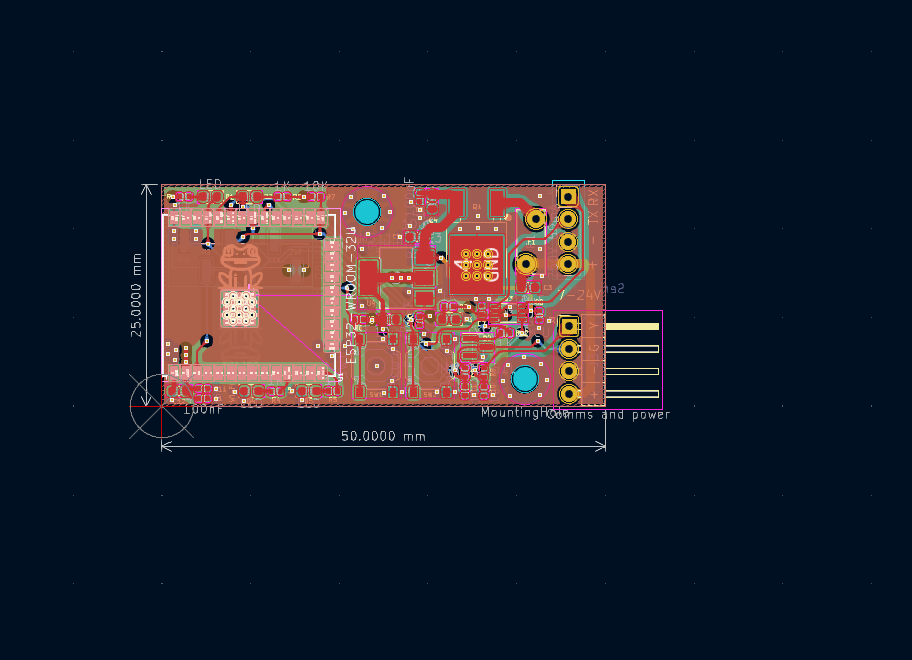
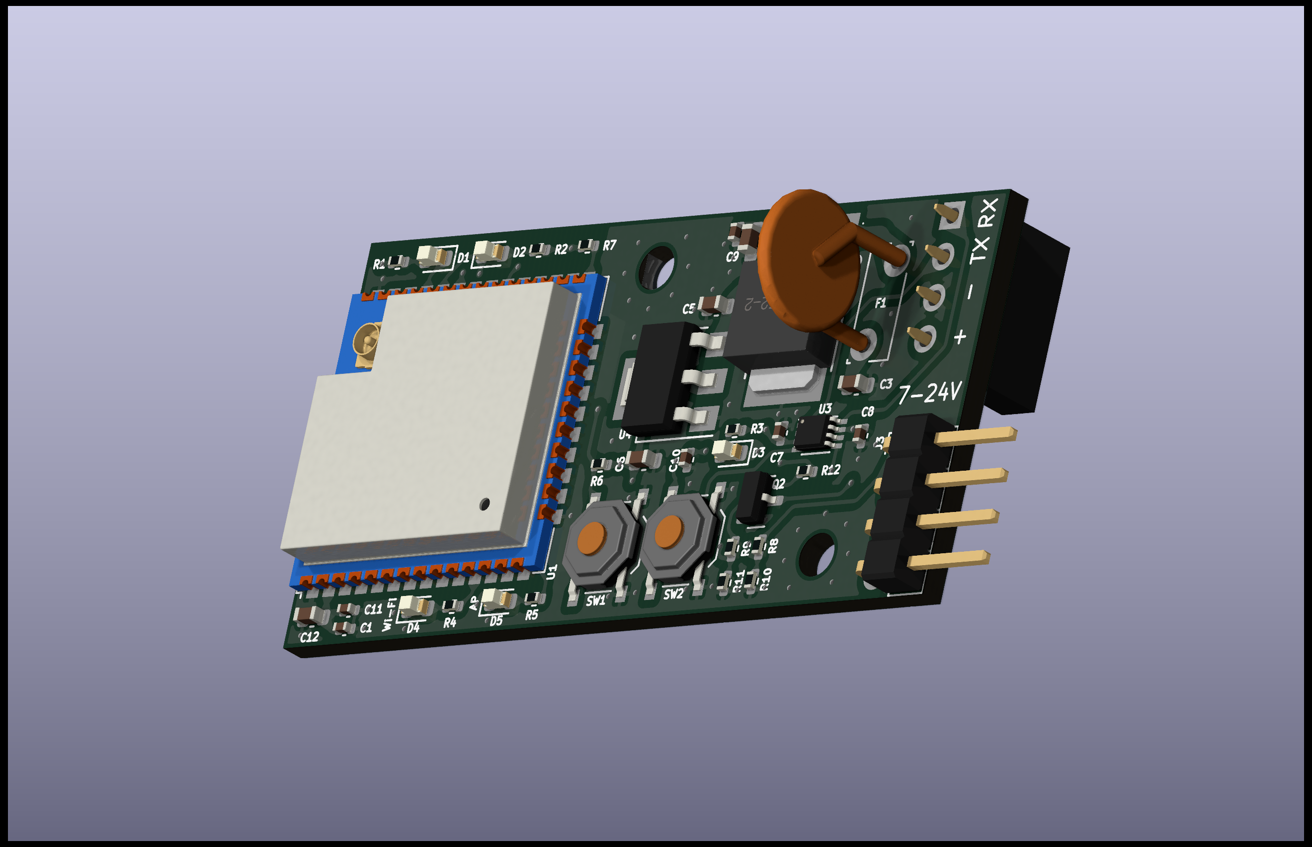
Esp ip is an open-source printed circuit board by wolffshots, from the wolffshots/esp-ip repository on GitHub, published under the MIT licence. It is a 4-layer board of 50 × 25 mm with 43 parts on 49 nets, routed with 206 tracks and 102 vias.
It is built around the ESP32-WROOM-32U, AMS1117-3.3 and TXS0102DCU, with the L78M05ABDT-TR and MMBT5551L among its other parts. Its parts include 12 resistors, 11 capacitors, 5 diodes, 3 ICs and 3 connectors. It belongs with the interfaces and adapters boards and the ESP32 boards of this library.


This project is a hardware solution that leverages the power of the ESP32 to bridge local communication interfaces, such as serial and (in the future) I2C, to a WiFi network. It allows devices with traditional communication interfaces to be accessed and controlled over WiFi.
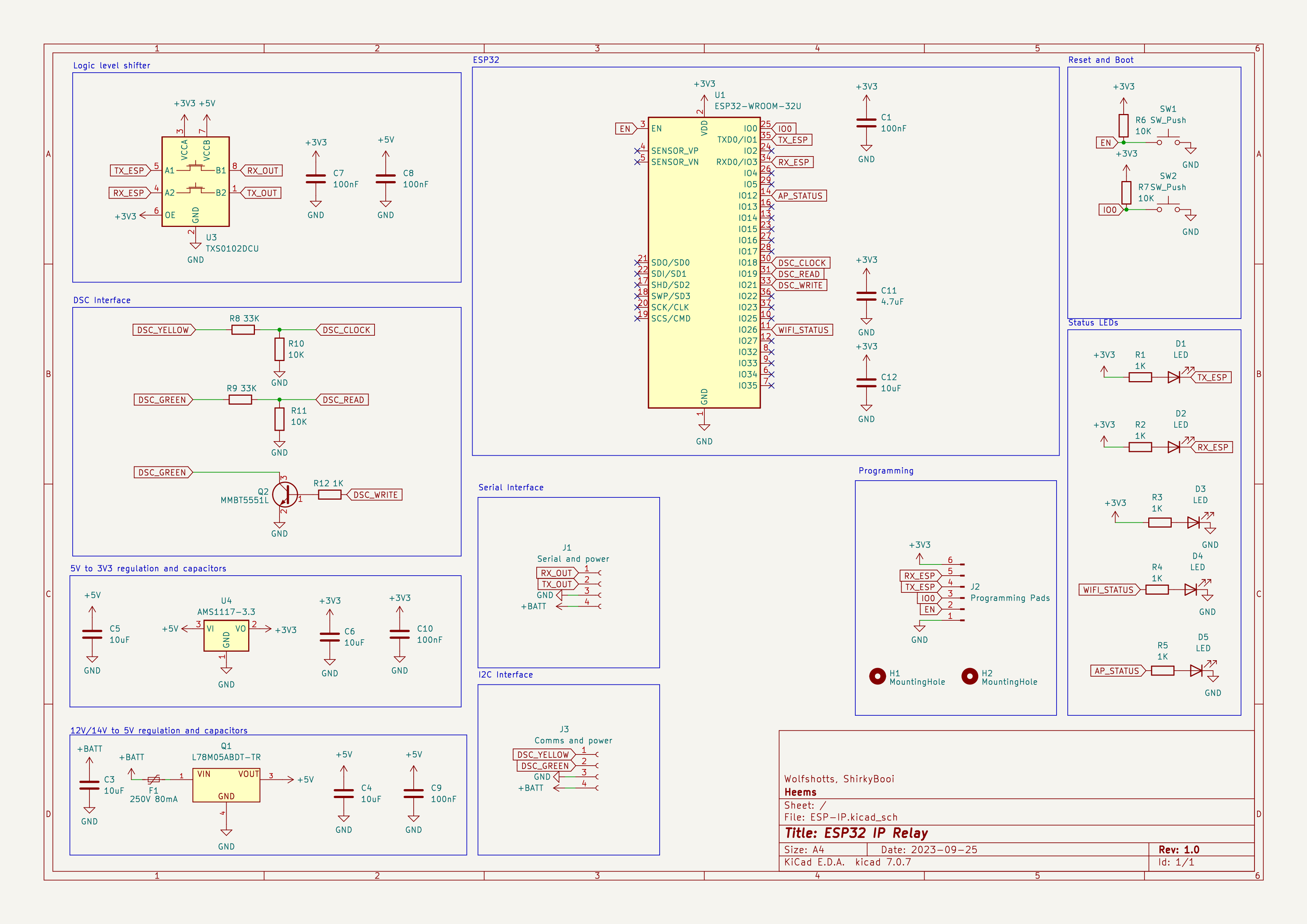
Interface Bridging: Convert and expose devices using:
WiFi Connectivity:
Status Indicators:
Details about how users can configure the firmware for specific WiFi networks, adjust baud rates for serial communication, or other configuration details.
We welcome contributions! Please read the CONTRIBUTING.md for details on submitting pull requests to us.
This project is licensed under the XYZ License - see the LICENSE.md file for details.
| Qty | Value | Footprint | References |
|---|---|---|---|
| 6 | 1K | Resistor_SMD:R_0402_1005Metric | R1, R2, R3, R4, R5, R12 |
| 5 | 100nF | Capacitor_SMD:C_0402_1005Metric | C1, C7, C8, C9, C10 |
| 5 | 10uF | Capacitor_SMD:C_0603_1608Metric | C3, C4, C5, C6, C12 |
| 5 | LED | LED_SMD:LED_0603_1608Metric | D1, D2, D3, D4, D5 |
| 4 | 10K | Resistor_SMD:R_0402_1005Metric | R6, R7, R10, R11 |
| 2 | 33K | Resistor_SMD:R_0402_1005Metric | R8, R9 |
| 2 | LOGO | Images:frog | G***, G*** |
| 2 | MountingHole | MountingHole:MountingHole_2.7mm_M2.5 | H1, H2 |
| 2 | SW_Push | Button_Switch_SMD:SW_Push_1P1T_XKB_TS-1187A | SW1, SW2 |
| 1 | 250V 80mA | Fuse:Fuse_Bourns_MF-RG300 | F1 |
| 1 | 4.7uF | Capacitor_SMD:C_0402_1005Metric | C11 |
| 1 | AMS1117-3.3 | Package_TO_SOT_SMD:SOT-223-3_TabPin2 | U4 |
| 1 | Comms and power | Connector_PinHeader_2.54mm:PinHeader_1x04_P2.54mm_Horizontal | J3 |
| 1 | ESP32-WROOM-32U | RF_Module:ESP32-WROOM-32UE | U1 |
| 1 | L78M05ABDT-TR | JLC:TO-252-2_L6.5-W6.1-P4.58-LS10.0-TL | Q1 |
| 1 | MMBT5551L | Package_TO_SOT_SMD:SOT-23 | Q2 |
| 1 | Programming Pads | Connector_PinHeader_2.54mm:PinHeader_1x06_P2.54mm_Vertical_SMD_Pin1Left | J2 |
| 1 | Serial and power | Connector_PinSocket_2.54mm:PinSocket_1x04_P2.54mm_Vertical | J1 |
| 1 | TXS0102DCU | Package_SO:VSSOP-8_2.3x2mm_P0.5mm | U3 |
It measures 50 × 25 mm and has 4 copper layers, 1.61 mm thick.
43 parts, built around the ESP32-WROOM-32U, AMS1117-3.3, TXS0102DCU and L78M05ABDT-TR. The full list of its parts is on this page, with links to each part's symbol and footprint where PCBKit's library has them.
From the wolffshots/esp-ip repository on GitHub, at the commit this page was made from: the board is ESP-IP.kicad_pcb and its schematic ESP-IP.kicad_sch. PCBKit opens the board in the browser, with nothing to install.
Its repository publishes it under the MIT licence: you may reuse it on that licence's terms (keep the author's notice, and for a copyleft licence share your changes alike).
Churrosoft/OpenEFI-PCB
Coleccion de PCB y planos recomendados para montar una OpenEFI

Churrosoft/uEFI-v6.x
Speeduino compatible board, x4 ignition channels, x4 injection channels, 2&4 wire IAC


Hasenpups/WLED_All-in-one_ESP32_Controller
This work is licensed under a [Creative Commons Attribution-NonCommercial-ShareAlike 4.0 International License][cc-by-nc-sa].

jarrod89/pocketPSU
Input1: - Output1 can be used to supply pocketPSU via a battery - Optional battery charging capability (addon board with BMS)


Stary2001/hdmi-switch
I couldn't find one of these easily, so I decided to make one myself.