2 layers150 × 77 mm

 wlowi/TXos3
RC Transmitter Software
Txboardmega is an open-source printed circuit board by wlowi, from the wlowi/TXos repository on GitHub, published under the MIT licence. It is a 2-layer board of 86.4 × 99.6 mm with 37 parts on 97 nets, routed with 400 tracks and 0 vias.
Its parts include 21 connectors, 4 resistors, 2 capacitors, 2 transistors and 2 switches.
Diese Software ist ein Beispiel für eine RC Sender firmware.
Es wird keine Haftung für Schäden jeglicher Art übernommen.
Bitte beachten Sie die Lizenz.
This is an example of a RC transmitter software.
In no event shall the authors or copyright holders be liable for any claim, damage or other liability.
Please obey the license.
Achtung: Crossfire Protokoll ist neu und noch nicht vollständig getestet.
Achtung: EXPERIMENTELL UND UNGETESTED, NICHT BENUTZEN!
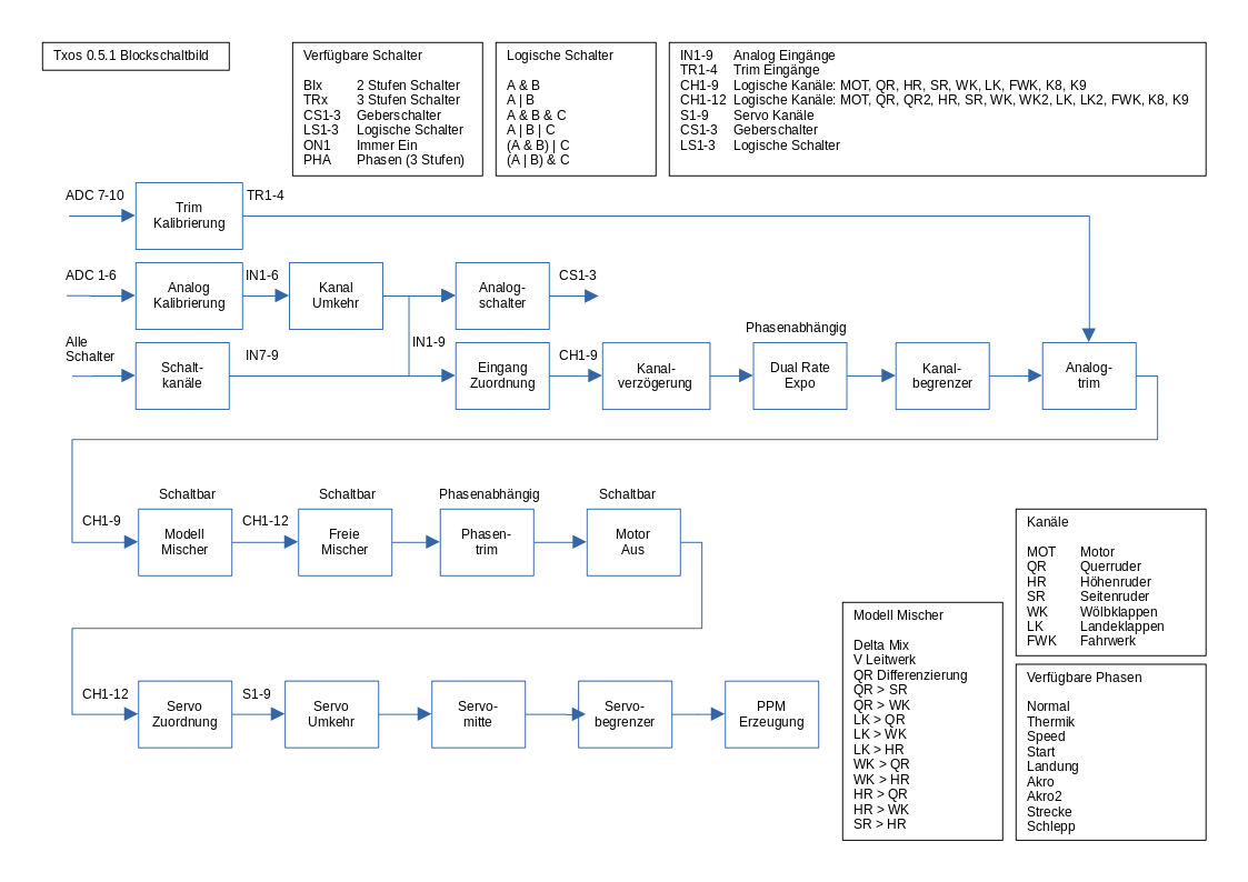
0.5.19 Some UI improvements.
       Keep value of logical "Mot" channel to correct value if engine cut is enabled.
0.5.18 CRSF and Spektrum Telemetry. First cut.
0.5.17 Disable sleep. Fix input names array.
0.5.16 CRSF Protokol
0.5.15 Serielles Spektrum Protokol
0.5.14 internes Release
0.5.13 Notorstart Modul
0.5.12 Veränderte schaltung der Flugphasen
0.5.11 Logische Schalter: invertierte Schalter.
0.5.10 Timer wahlweise Gasabhängig.
       Alle Schalter in SWx umbenannt.
0.5.9 Landeklappen Modul.
0.5.8 Watchdog fix beim schreiben ins EEPROM und serial I/O
0.5.7 Servo Verzögerung Modul.
0.5.6 Servo Weg Modul.
0.5.5 Experimental ESP 32 support.
0.5.4 External user terminal support.
0.5.3 Experimental external user terminal support.
0.5.2 Template based configuration
0.5.1 Modul import fixed. Geber Weg getrennt pos. und neg.
0.5.0 Modell import/export. Modell management.Benötigte Arduino Libraries
cd TXos
./mklinks atmega2560
Dieses Kommando verlinkt die Dateien im src Verzeichnis nach TXos.
Fall noch keine lokale Konfigurationsdtei TXosLocalConfig.h existiert wird diese von einer Musterdatei kopiert und muss an die eigen Hardware konfiguration angepasst werden.
Mit der Arduino IDE kann dann in diesem Verzeichnis TXos compiliert werden.
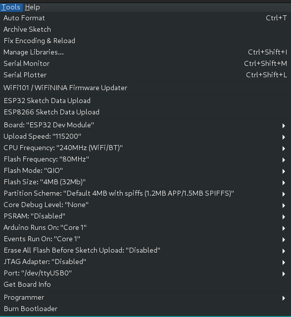
Notwendige Einstellungen der Arduino IDE
TO_BE_COMPLETED
Benötigte Arduino Libraries
cd TXos
./mklinks esp32
Mit der Arduino IDE kann dann in diesem Verzeichnis TXos compiliert werden.
Notwendinge Einstellungen der Arduino IDE
Wechsel zu Verzeichnis TXos/TXos
Unter Linux ./mklinks.sh <Platform>
ausführen.
Unter Windows mkcopy.bat <Platform>
ausführen.
Als Platform wird zur Zeit nur atmega2560 unterstützt.
Existiert noch keine Datei TXosLocalConfig.h wird diese aus TXosLocalConfig.template neu erzeugt.
Konfiguration in TXosLocalConfig.h anpassen.
Hier werden eingestellt:
Beispiel:
$ ./mklinks.sh atmega2560
Configuring for atmega2560
Link from ../src
   ../src/Comm.cpp  =>  Comm.cpp
   ../src/ConfigBlock.cpp  =>  ConfigBlock.cpp
   ../src/HomeScreen.cpp  =>  HomeScreen.cpp
  .
  .
  .
   atmega2560/OutputImpl.h  =>  OutputImpl.h
   atmega2560/PortsImpl.h  =>  PortsImpl.h

Local config does not exist.
A new TXosLocalConfig.h has been generated by copying the template file.
Please modify your local config to your needs.Der Simulator verwendet die wxWidgets library. Zum installieren:
apt install gcc make libwxgtk3.0-gtk3-dev

cd src
make clean
make -j
./TXosTest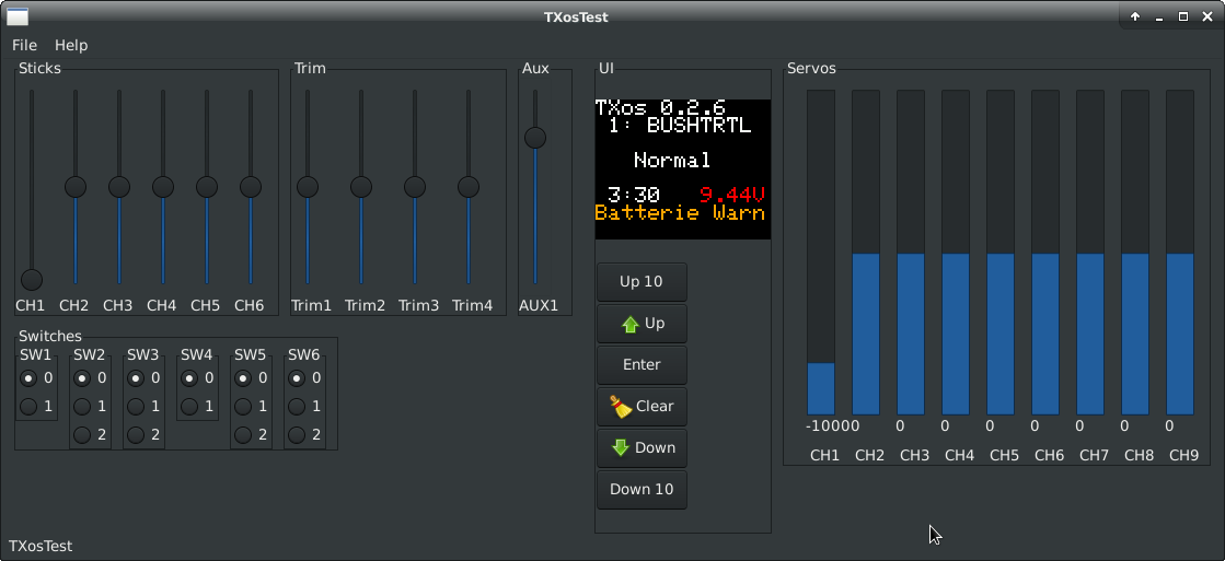
cd test
make clean
make -j unittest
./TXosUnitTest
Achtung: make clean unittest funktioniert nicht!
| Qty | Value | Footprint | References |
|---|---|---|---|
| 4 | MountingHole_3.2mm_M3_DIN965_Pad | MountingHole:MountingHole_3.2mm_M3_DIN965_Pad | REF1, REF2, REF3, REF4 |
| 3 | 10k | Resistor_THT:R_Axial_DIN0207_L6.3mm_D2.5mm_P10.16mm_Horizontal | R1, R3, R4 |
| 2 | BC107 | Package_TO_SOT_THT:TO-18-3 | Q1, Q2 |
| 1 | 100uF | Capacitor_THT:CP_Radial_D6.3mm_P2.50mm | C2 |
| 1 | 10uF | Capacitor_THT:CP_Radial_D5.0mm_P2.00mm | C3 |
| 1 | 22k | Resistor_THT:R_Axial_DIN0207_L6.3mm_D2.5mm_P10.16mm_Horizontal | R2 |
| 1 | ARD_Mega2560_pro | joy-it:ARD_Mega2560_pro | U1 |
| 1 | Analog 1 | Connector_JST:JST_EH_B3B-EH-A_1x03_P2.50mm_Vertical | J3 |
| 1 | Analog 2 | Connector_JST:JST_EH_B3B-EH-A_1x03_P2.50mm_Vertical | J4 |
| 1 | Analog 3 | Connector_JST:JST_EH_B3B-EH-A_1x03_P2.50mm_Vertical | J5 |
| 1 | Analog 4 | Connector_JST:JST_EH_B3B-EH-A_1x03_P2.50mm_Vertical | J6 |
| 1 | Analog 5 | Connector_JST:JST_EH_B3B-EH-A_1x03_P2.50mm_Vertical | J7 |
| 1 | Analog 6 | Connector_JST:JST_EH_B3B-EH-A_1x03_P2.50mm_Vertical | J8 |
| 1 | Bind | Connector_JST:JST_EH_B3B-EH-A_1x03_P2.50mm_Vertical | J21 |
| 1 | Bind | Relay_THT:Relay_DPDT_FRT5 | K2 |
| 1 | Buzzer | Buzzer_Beeper:Buzzer_15x7.5RM7.6 | BZ1 |
| 1 | Display | Connector_JST:JST_EH_B8B-EH-A_1x08_P2.50mm_Vertical | J2 |
| 1 | Encoder | Connector_JST:JST_EH_B5B-EH-A_1x05_P2.50mm_Vertical | J15 |
| 1 | HF on | Relay_THT:Relay_DPDT_FRT5 | K1 |
| 1 | Power | Connector_JST:JST_EH_B2B-EH-A_1x02_P2.50mm_Vertical | J1 |
| 1 | Switch 1 | Connector_JST:JST_EH_B3B-EH-A_1x03_P2.50mm_Vertical | J9 |
| 1 | Switch 2 | Connector_JST:JST_EH_B3B-EH-A_1x03_P2.50mm_Vertical | J10 |
| 1 | Switch 3 | Connector_JST:JST_EH_B3B-EH-A_1x03_P2.50mm_Vertical | J11 |
| 1 | Switch 4 | Connector_JST:JST_EH_B3B-EH-A_1x03_P2.50mm_Vertical | J12 |
| 1 | Switch 5 | Connector_JST:JST_EH_B3B-EH-A_1x03_P2.50mm_Vertical | J13 |
| 1 | Switch 6 | Connector_JST:JST_EH_B3B-EH-A_1x03_P2.50mm_Vertical | J14 |
| 1 | TX Module | Connector_JST:JST_EH_B5B-EH-A_1x05_P2.50mm_Vertical | J16 |
| 1 | Trim 1 | Connector_JST:JST_EH_B3B-EH-A_1x03_P2.50mm_Vertical | J17 |
| 1 | Trim 2 | Connector_JST:JST_EH_B3B-EH-A_1x03_P2.50mm_Vertical | J18 |
| 1 | Trim 3 | Connector_JST:JST_EH_B3B-EH-A_1x03_P2.50mm_Vertical | J19 |
| 1 | Trim 4 | Connector_JST:JST_EH_B3B-EH-A_1x03_P2.50mm_Vertical | J20 |
It measures 86.4 × 99.6 mm and has 2 copper layers, 1.6 mm thick.
37 parts. The full list of its parts is on this page, with links to each part's symbol and footprint where PCBKit's library has them.
From the wlowi/TXos repository on GitHub, at the commit this page was made from: the board is txboardmega/txboardmega.kicad_pcb and its schematic txboardmega/txboardmega.kicad_sch. PCBKit opens the board in the browser, with nothing to install.
Its repository publishes it under the MIT licence: you may reuse it on that licence's terms (keep the author's notice, and for a copyleft licence share your changes alike).


hoglet67/RGBtoHDMI
Bare-metal Raspberry Pi project that provides pixel-perfect sampling of Retro Computer RGB/YUV video and conversion to HDMI

hackclub/OnBoard
💡 Join 1,000 teenagers and make your first PCB with a $100 grant!

FreeYourStream/freedeck-hardware
all the stuff you need to build your own FreeDeck

stuartpittaway/diyBMS
Do it yourself battery management system for Lithium ion battery packs/cells

Pwnsat/FlatSat
Flatsat v1.0 is a hardware based platform for aerospace cybersecurity research


vsfteam/vsf
Versaloon Software Framework -- a tiny preemptive-capable event-driven incremental software framework for embedded systems