2 layers
Encoder
byrantech/laptop
anyon_e, a highly integrated, high end, open source laptop. Attempt the impossible.
7 parts4.3kMIT

 wldd22/tetra-clock
A custom alarm clock loosely based on the Blare guide
Tetra clock is an open-source printed circuit board by wldd22, from the wldd22/tetra-clock repository on GitHub. It is a 2-layer board of 70 × 70 mm with 7 parts on 18 nets, routed with 27 tracks and 0 vias.
It belongs with the lEDs and displays boards and the ESP32 boards of this library.
A custom alarm clock loosely based on the Blare guide.
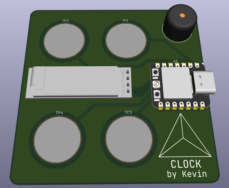
PCB made using KiCAD
Firmware uses CircuitPython
This PCB is a simple alarm clock display I designed to show the date and time, and set alarms.
Features:
When I saw Mitxela's Precision Clock, I was inspired to design a custom clock myself. I wanted mine to be much more compact, like something you could carry around in a pocket, but that still looked cool and worked well. I used capacitive pads because it's an easy way I've found to make button inputs that, one, don't require any extra components, and two, are as compact as possible, being just as slim as the board itself.
This project was originally made for week 1 (PCB week) of Hack Club's Half Life. The idea and some of the components used were based on the Blare guide, but the actual design and the firmware was created from scratch by me.
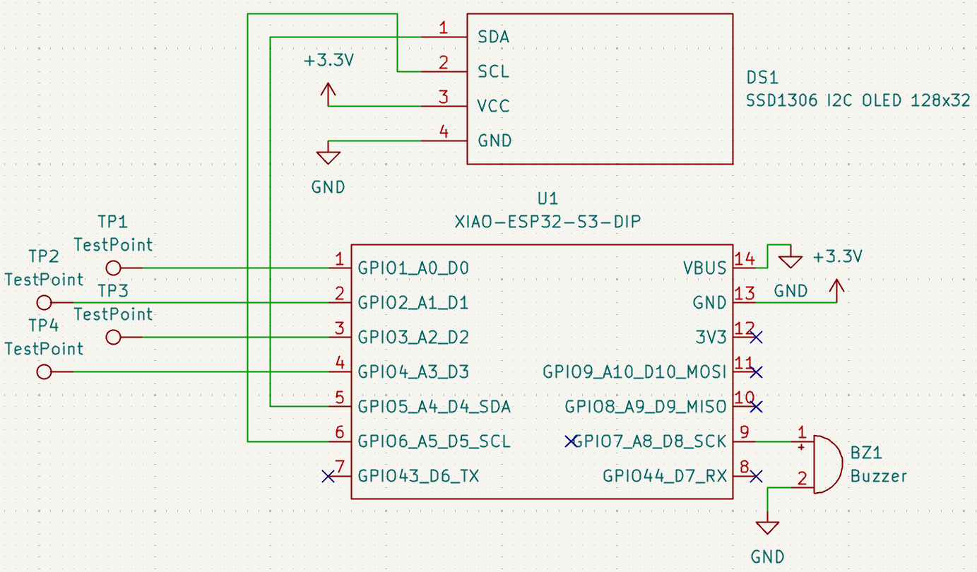
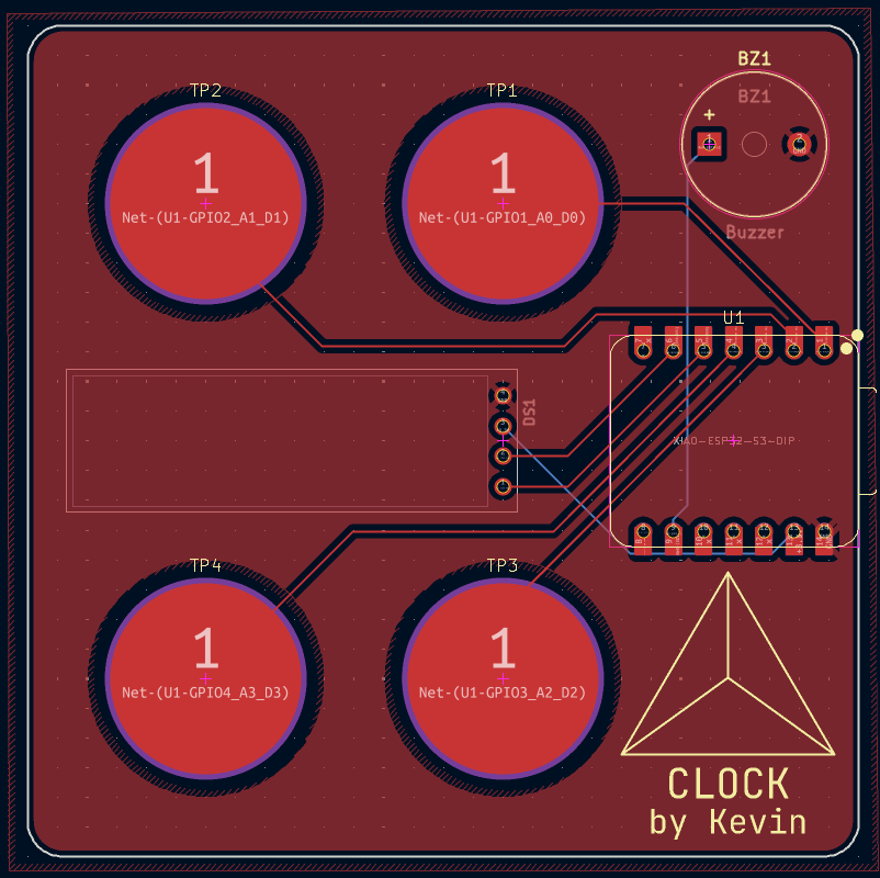
| Qty | Value | Footprint | References |
|---|---|---|---|
| 4 | TestPoint | Capacitive Pads:CAP_CIRCLE_PAD | TP1, TP2, TP3, TP4 |
| 1 | Buzzer | Buzzer_Beeper:Buzzer_12x9.5RM7.6 | BZ1 |
| 1 | SSD1306 I2C OLED 128x32 | SSD1306 OLED:SSD1306 I2C OLED 128x32 | DS1 |
| 1 | XIAO-ESP32-S3-DIP | Seeed Studio XIAO Series Library:XIAO-ESP32-S3-DIP | U1 |
It measures 70 × 70 mm and has 2 copper layers, 1.6 mm thick.
7 parts. The full list of its parts is on this page, with links to each part's symbol and footprint where PCBKit's library has them.
From the wldd22/tetra-clock repository on GitHub, at the commit this page was made from: the board is pcb/tetra-clock.kicad_pcb and its schematic pcb/tetra-clock.kicad_sch. PCBKit opens the board in the browser, with nothing to install.
Its repository states no licence, so its author keeps all rights: ask wldd22 before reusing the design.
byrantech/laptop
anyon_e, a highly integrated, high end, open source laptop. Attempt the impossible.


AxxAxx/AxxSolder
STM32 Based soldering station for JBC cartridges, 9-24 VDC and USB-PD power


jamro/tiny-engineer
A small desktop robot that brings an AI coding assistant to life, physically acting out when it reads files, thinks, writes code, and finishes work.

hoglet67/RGBtoHDMI
Bare-metal Raspberry Pi project that provides pixel-perfect sampling of Retro Computer RGB/YUV video and conversion to HDMI
