
2 layers40.6 × 110 mm
Europi surface mount
Allen-Synthesis/EuroPi
EuroPi: A reprogrammable Eurorack module based on the Raspberry Pi Pico
92 parts584CC0-1.0

 WizardTim/AR0004-R12
10W D50 & D65 Standard Illuminant
AR0004-R1 is an open-source printed circuit board by WizardTim, from the WizardTim/AR0004-R1 repository on GitHub, published under the GPL-3.0 licence. It is a 2-layer board of 100 × 50 mm with 54 parts on 10 nets, routed with 306 tracks and 277 vias.
It is built around the L7805. Its parts include 22 diodes, 10 capacitors, 6 connectors, 5 resistors and 3 ICs. It belongs with the lEDs and displays boards of this library.
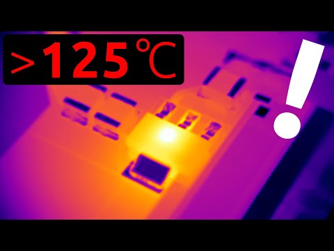
PCB design files for 10W D50/D65 (5000K/6500K ANSI approximate) standard illuminant modular LED panels. Note any 3528 PLCC LED will suffice provided forward voltage and maximum current are accounted for.
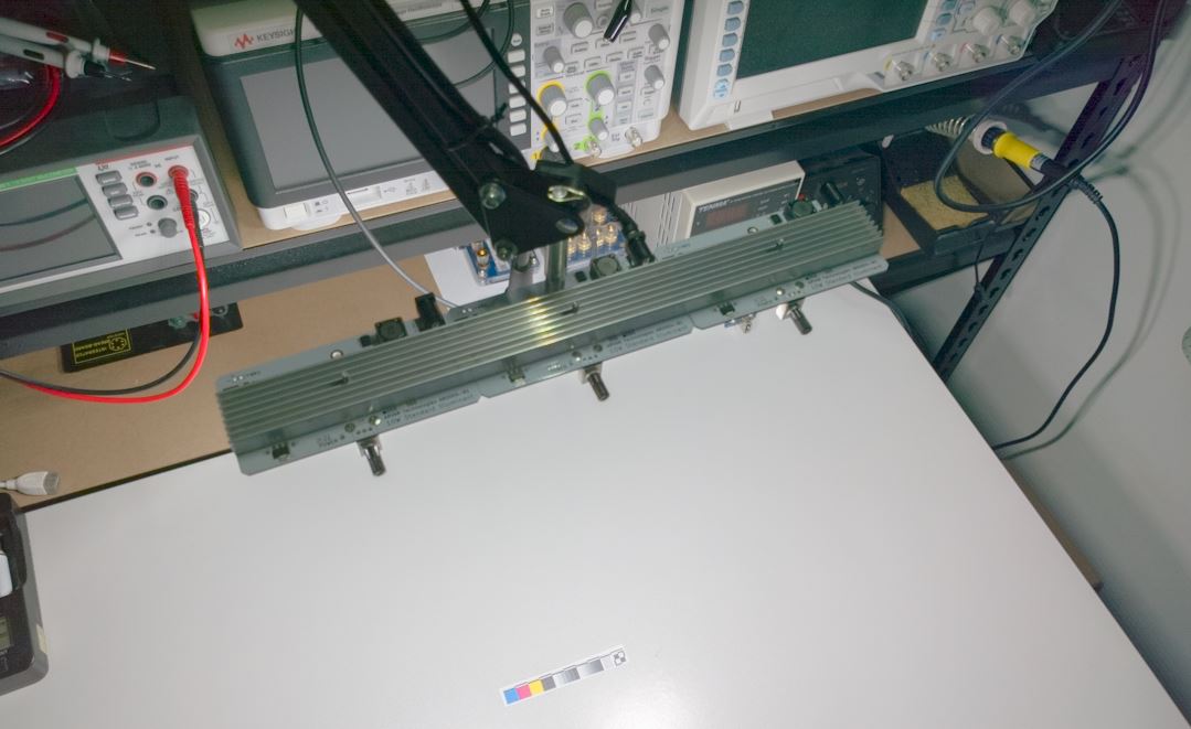
| Qty | Value | Footprint | References |
|---|---|---|---|
| 20 | EAHC | LEDs:LED_PLCC_2835 | D1, D2, D3, D4, D5, D10, D12, D13, D14, D15, D16, D17, D18, D19, D20, D21 +4 |
| 6 | M3 Mounting Hole | Mounting_Holes:MountingHole_3.2mm_M3_ISO14580_Pad | MK1, MK2, MK3, MK4, MK5, MK6 |
| 4 | 100n | Resistors_SMD:R_0603 | C1, C2, C3, C4 |
| 4 | 10u | Resistors_SMD:R_1210 | C5, C6, C7, C8 |
| 3 | 0.1 | Resistors_SMD:R_1206 | R2, R3, R4 |
| 2 | + | Measurement_Points:Test_Point_Keystone_5019_Minature | J1, J2 |
| 2 | - | Measurement_Points:Test_Point_Keystone_5019_Minature | J4, J5 |
| 2 | 1u | Resistors_SMD:R_1206 | C9, C14 |
| 1 | 10k | Potentiometers:Potentiometer_Alps_RK09K_Vertical | RV1 |
| 1 | 1k | Resistors_SMD:R_0603 | R5 |
| 1 | 2.7k | Resistors_SMD:R_0603 | R1 |
| 1 | 33u | Choke_SMD:Choke_SMD_12x12mm_h4.5mm | L1 |
| 1 | 5.5mm | Connectors:BARREL_JACK | J3 |
| 1 | AL8843MP | Housings_SOIC:HTSOP-8-1EP_3.9x4.9mm_Pitch1.27mm_ThermalVias_LargeCopper | U3 |
| 1 | AP1117-33 | TO_SOT_Packages_SMD:SOT-223-3_TabPin2 | U1 |
| 1 | BLUE | LEDs:LED_0603 | D22 |
| 1 | FAN | Pin_Headers:Pin_Header_Straight_1x02_Pitch2.54mm | J6 |
| 1 | L7805 | TO_SOT_Packages_SMD:TO-252-2 | U2 |
| 1 | Schottky | Diodes_SMD:D_SMB | D11 |
It measures 100 × 50 mm and has 2 copper layers, 1.6 mm thick.
54 parts, built around the L7805. The full list of its parts is on this page, with links to each part's symbol and footprint where PCBKit's library has them.
From the WizardTim/AR0004-R1 repository on GitHub, at the commit this page was made from: the board is AR0004-R1.kicad_pcb. PCBKit opens the board in the browser, with nothing to install.
Its repository publishes it under the GPL-3.0 licence: you may reuse it on that licence's terms (keep the author's notice, and for a copyleft licence share your changes alike).
Allen-Synthesis/EuroPi
EuroPi: A reprogrammable Eurorack module based on the Raspberry Pi Pico

peterheinrich/InternetOverSpaghetti
Transmitting IP packages over a pair of spaghetti thus demonstrating how media independent IP really is.


Tircown/ERCF-easy-brd
More informations on how to reset for flashing:\ https://wiki.seeedstudio.com/Seeeduino-XIAO/#enter-bootloader-mode

matthewcieplak/super-sixteen
Code and schematics for the Super Sixteen Eurorack sequencer

NikodemBartnik/Mini-Mars-Rover
Educational robotic platform made to look like a mini mars rover

starlightk7/OpenSFC
OSHW Reproduction Parts related to the Super Famicom / Super Nintendo game console

Redherring32/OpenTendo-TopLoader
An Open Source HardWare (OSHW) recreation of the 1993 toploading NES motherboard (Also known as NES-101)