
2 layers208.8 × 396.9 mm
Ferris
pierrechevalier83/ferris
A low profile split keyboard designed to satisfy one single use case elegantly
145 parts1.3k
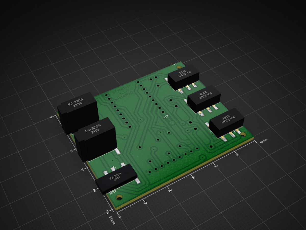
 wistoff/io-patchbox
ESP32-S3-based 3-channel sensor-to-actor controller for interactive art therapy, featuring automatic sensor detection and proportional PWM output.
Io patchbox is an open-source printed circuit board by wistoff, from the wistoff/io-patchbox repository on GitHub. It is a 2-layer board of 60 × 51 mm with 22 parts on 30 nets, routed with 210 tracks and 24 vias.
It is built around the PJ-320A. Its parts include 6 ICs, 3 resistors, 3 diodes, 3 transistors and 2 connectors. It belongs with the sensors and measurement boards of this library.
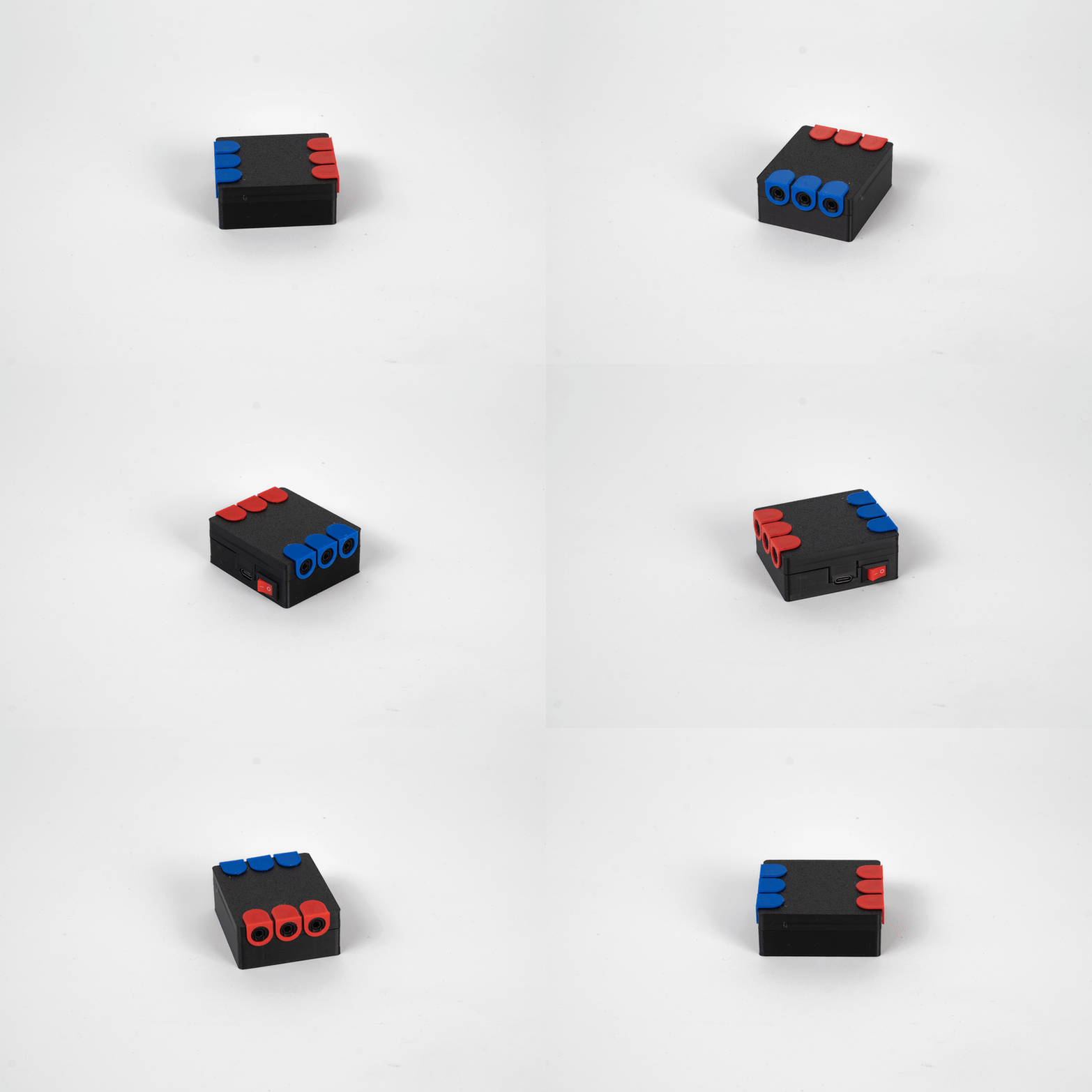
A 3-channel sensor-to-actor controller designed for Manou Wistoff's approach to phygitale Kunsttherapie, part of her master thesis at Alanus Kunsthochschule.
Building on the concept of phygitale Kunsttherapie, the I/O Patchbox makes the digital tangible by bringing interactive electronics into the physical space. Interactive electronic components become material in the art therapy process, just like clay, paint, or fabric. Through process-oriented creating (Tinkering), clients combine classical crafting materials with sensors and actors connected through the I/O Patchbox, resulting in interactive artworks.
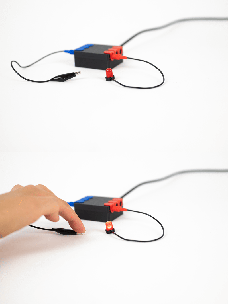
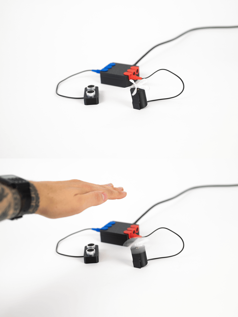
The I/O Patchbox is built on an ESP32-S3 Mini with a custom carrier PCB. Each channel auto-detects its sensor type at boot (ultrasonic HC-SR04 or capacitive touch) and drives an output (LED, motor) proportionally via PWM through a low-side NPN transistor stage.
i-o-patchbox/
├── firmware/
│   ├── esp32s3-mini/            # current target (LOLIN ESP32-S3 Mini)
│   │   ├── src/main.cpp
│   │   ├── platformio.ini
│   │   └── PINOUT.md
│   └── esp32-wroom-dev-board/   # earlier prototype (ESP32 WROOM DevKit)
│       ├── src/main.cpp
│       ├── platformio.ini
│       └── PINOUT.md
├── hardware/                    # KiCad 10 PCB project
│   ├── pcb.kicad_sch             # schematic
│   ├── pcb.kicad_pcb             # board layout (single-sided, home-etched)
│   ├── pcb.kicad_pro             # project file
│   ├── libs/PJ-320A/             # TRRS jack symbol + footprint library
│   ├── gerber/                   # fabrication outputs
│   ├── exports/                  # SVG renders, drill maps
│   ├── backups/                  # KiCad auto-backups
│   └── schaltplan.pdf            # schematic export
└── enclosure/                   # 3D-printable cases (OBJ)
    ├── cable-plug.obj            # cable strain relief (used by all sensors and actors)
    ├── patchbox/                 # main device enclosure
    │   ├── top.obj
│ ├── bottom.obj| Channel | Trigger / Touch | Echo | Actor |
|---|---|---|---|
| 1 | GP1 | GP7 | GP10 |
| 2 | GP2 | GP8 | GP11 |
| 3 | GP3 | GP9 | GP12 |
| Switch | - | - | GP13 |
All sensors connect via 4-pole TRRS jacks (PJ-320D). Wiring: Tip = +5V, Ring1 = TRIG, Ring2 = ECHO, Sleeve = GND.
Each channel auto-detects its sensor type at startup by probing for ultrasonic echoes. If none are found, it falls back to capacitive touch.
| Type | Part | How it works |
|---|---|---|
| Ultrasonic | HC-SR04 | Distance sensor (2-60 cm). All 4 TRRS conductors used. Output brightness is inversely proportional to distance. |
| Capacitive touch | Bare wire / crocodile cable | Connects to the ECHO pin (Ring2) only. Touch value increases on contact (ESP32-S3 behavior). Adaptive baseline with asymmetric smoothing. Slow ramp-up absorbs motor-stop noise while fast ramp-down keeps release responsive. Recalibrates each time the switch is toggled on. |
All actors connect via TRRS jacks. Wiring: Tip = +5V (always on), Sleeve = transistor collector (PWM-switched ground). Ring1/Ring2 unused.
The board provides a generic 5V PWM low-side driver per channel (2N2222 + 330R base resistor + 1N4007 flyback diode). The load type is adapted in the device cable with a series resistor, so no board changes are needed to swap between LEDs and motors.
| Load | Cable resistor | Notes |
|---|---|---|
| LED (red/yellow) | 150R series | ~20 mA at 5V, polarity matters (anode to Tip) |
| LED (green/blue/white) | 100R series | Higher Vf, ~18 mA |
| 5V motor | none | Direct connection, bare cable |
| 3V vibration motor | none | Runs off 5V directly, no series resistor |
PWM runs at 25 kHz (inaudible for motors), 8-bit resolution (0-255).
Requires PlatformIO.
cd firmware/esp32s3-mini
pio run -t upload
pio device monitorSingle-sided carrier PCB designed in KiCad 10 for home etching (toner transfer). All copper on F.Cu, SMD TRRS jacks, THT passives soldered from the top side.
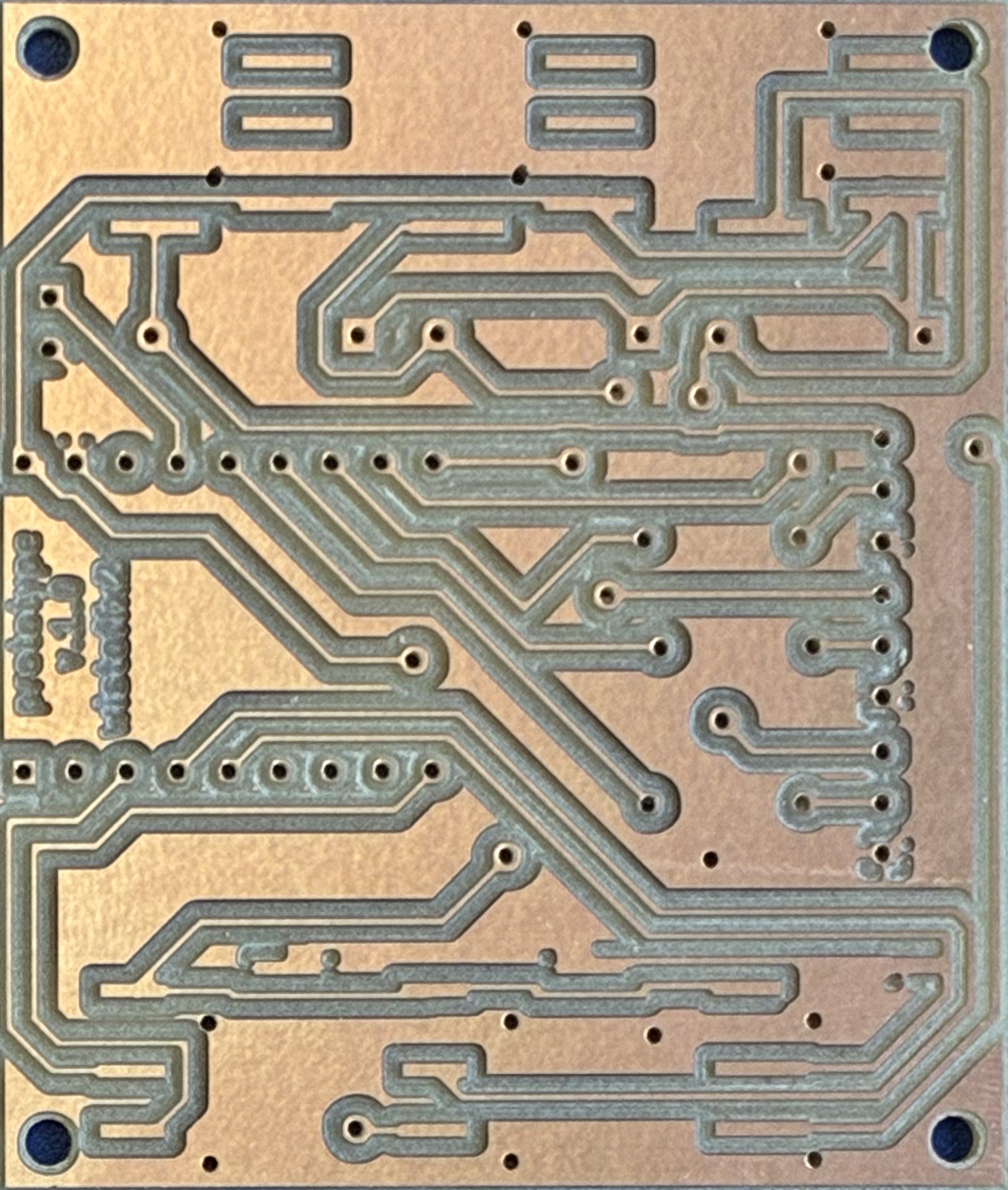
Key components: 3x PJ-320D TRRS jacks (sensor), 3x PJ-320D (actor), 3x 2N2222 NPN transistors, 3x 330R base resistors, 3x 1N4007 flyback diodes.
| Qty | Value | Footprint | References |
|---|---|---|---|
| 6 | PJ-320A | PJ-320A_Library:PJ-320D_SMD_remap | U2, U3, U4, U5, U6, U7 |
| 3 | 1N4007 | Diode_THT:D_DO-41_SOD81_P10.16mm_Horizontal | D1, D2, D3 |
| 3 | 2N2222 | Package_TO_SOT_THT:TO-92_Inline_Wide | Q1, Q2, Q3 |
| 3 | R | Resistor_THT:R_Axial_DIN0207_L6.3mm_D2.5mm_P7.62mm_Horizontal | R1, R2, R3 |
| 2 | Conn_01x11 | Connector_PinHeader_2.54mm:PinHeader_1x09_P2.54mm_Vertical | J1, J2 |
| 1 | SW_SPST | Connector_PinHeader_2.54mm:PinHeader_1x02_P2.54mm_Vertical | SW1 |
The 18 most common of 22 parts.
It measures 60 × 51 mm and has 2 copper layers, 1.6 mm thick.
22 parts, built around the PJ-320A. The full list of its parts is on this page, with links to each part's symbol and footprint where PCBKit's library has them.
From the wistoff/io-patchbox repository on GitHub, at the commit this page was made from: the board is hardware/pcb.kicad_pcb and its schematic hardware/pcb.kicad_sch. PCBKit opens the board in the browser, with nothing to install.
Its repository states no licence, so its author keeps all rights: ask wistoff before reusing the design.
pierrechevalier83/ferris
A low profile split keyboard designed to satisfy one single use case elegantly

softcomplex/Digirig-Mobile
Integrated digital modes interface for amateur radio

LouWii/ErgoMax
Custom ergo split keyboard project, based on ErgoDox, with hot swap sockets

DarcyJProjects/touchtone555
An open-source DIY, NE555-based analogue synthesizer - play notes with a stylus


piit79/mysteripad
A through-hole mechanical numpad with an extra row to match the Mysterium keyboard

