2 layers120.4 × 140.2 mm
Cncdriver3axis
acassis/simplemaker
This is an evolve from TheMarker2 CNC replacing the PIC microcontroller by an Atmega
68 parts2GPL-2.0
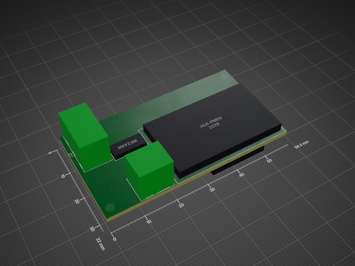
 willy40/UVTimer
ESP32-based BLE timer replacement for NE555 in UV nail lamps. Features Android app control and BT136 triac switching.
UVTimer is an open-source printed circuit board by willy40, from the willy40/UVTimer repository on GitHub, published under the MIT licence. It is a 2-layer board of 58.5 × 32 mm with 10 parts on 26 nets, routed with 41 tracks and 2 vias.
It is built around the HLK-PM03, CNY17-2 and IRFZ44N. Its parts include 4 resistors, 3 ICs, 2 connectors and 1 transistor. It belongs with the radio and wireless and lEDs and displays boards and the ESP32 and RISC-V boards of this library.






This project is a modern, BLE-controlled replacement for the traditional NE555 hardware timer used in UV nail lamps. It replaces the legacy analog timer with an ESP32 microcontroller, enabling precise wireless control via an Android application.
This project is designed to upgrade and replace the classic analog circuit based on the NE555 timer and BT134/BT136 triac. For a detailed breakdown of how the original UV lamps operate, their schematics, and common hardware issues, check out this excellent reference article:
├── include/            # ESP32: Header files (.h)
├── src/                # ESP32: Source code (.cpp)
├── platformio.ini      # ESP32: PlatformIO configuration file
├── .gitignore          # Git ignore rules
├── README.md           # Project documentation
└── Related/
    ├── Android/        # Android Studio project for the smartphone app
└── Kicad/ # KiCad schematic and PCB layout filesRelated/Kicad/ directory to view the schematic and PCB layout.Related/Android/ directory using Android Studio.This project is licensed under the MIT License - see the LICENSE file for details.
| Qty | Value | Footprint | References |
|---|---|---|---|
| 1 | 0 | Resistor_SMD:R_1206_3216Metric | R3 |
| 1 | 10K | Resistor_SMD:R_1206_3216Metric | R4 |
| 1 | 150 | Resistor_SMD:R_1206_3216Metric | R1 |
| 1 | 220V | TerminalBlock_MetzConnect:TerminalBlock_MetzConnect_Type094_RT03502HBLU_1x02_P5.00mm_Horizontal | J2 |
| 1 | 330 | Resistor_SMD:R_1206_3216Metric | R2 |
| 1 | CNY17-2 | Package_DIP:SMDIP-6_W9.53mm_Clearance8mm | U2 |
| 1 | ESP32-C3_SUPERMINI_TH | MODULE_ESP32-C3_SUPERMINI:MODULE_ESP32-C3_SUPERMINI | U1 |
| 1 | HLK-PM03 | Converter_ACDC:Converter_ACDC_Hi-Link_HLK-PMxx | U3 |
| 1 | IRFZ44N | Package_TO_SOT_THT:TO-220-3_Vertical | Q1 |
| 1 | ~ | TerminalBlock_MetzConnect:TerminalBlock_MetzConnect_Type094_RT03503HBLU_1x03_P5.00mm_Horizontal | J3 |
It measures 58.5 × 32 mm and has 2 copper layers, 1.6 mm thick.
10 parts, built around the HLK-PM03, CNY17-2 and IRFZ44N. The full list of its parts is on this page, with links to each part's symbol and footprint where PCBKit's library has them.
From the willy40/UVTimer repository on GitHub, at the commit this page was made from: the board is Related/KiCad/UVTimer/UVTimer.kicad_pcb and its schematic Related/KiCad/UVTimer/UVTimer.kicad_sch. PCBKit opens the board in the browser, with nothing to install.
Its repository publishes it under the MIT licence: you may reuse it on that licence's terms (keep the author's notice, and for a copyleft licence share your changes alike).
acassis/simplemaker
This is an evolve from TheMarker2 CNC replacing the PIC microcontroller by an Atmega

KP1533TM2/e003-capstan
Блок управления ведущим двигателем Олимпа 003 с ФАПЧ, основанный на БУВД самодельного магнитофона TK-140 leoniv


jibrilsharafi/EnergyMe-Home
Smart energy meter capable of monitoring up to 16 channels. Supports MQTT, REST API, Modbus TCP, InfluxDB, AWS IoT Core. Friendly UI and fully open source (PCB, schematics, components, source code)

voltlog/Valve-Actuator
If you are looking for sources of previous revisions (revA, revB, revC) checkout the different branches of this repo.

tomikaa87/esp-thermostat
Smart WiFi thermostat based on the well-known ESP8266 SoC.
