2 layers103 × 30.5 mm
 WilliTourt/ArmSync4
6-DOF humanoid robotic arm. Controlled by Renesas RA8P1 MCU
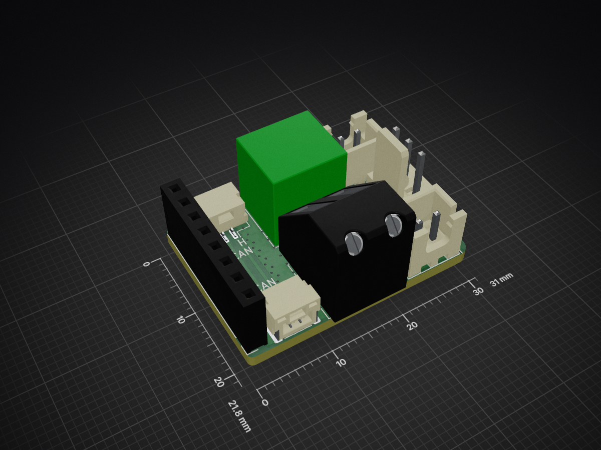
Renesas ArmSync CAN Connector is an open-source printed circuit board by WilliTourt, from the WilliTourt/ArmSync repository on GitHub, published under the MIT licence. It is a 2-layer board of 31 × 21.8 mm with 9 parts on 10 nets, routed with 18 tracks and 139 vias.
It belongs with the robots and motor control boards of this library.
ArmSync is a six-degree-of-freedom robotic arm project using a dual-IMU master-slave wireless teleoperation scheme. It was originally developed for the Renesas Electronics Competition.
This repository contains mechanical design files, PCBs, embedded firmware, kinematics tools, and UI resources. You are welcome to reference the designs and code, but please note that the project is still being organized and iterated.
The design report PDF file is here:Design Report
⚠ WARNING: The software resources in this repository are provided for reference only.
ArmSync is a six-degree-of-freedom robotic arm primarily made from PLA 3D-printed parts. It contains six mechanical joints, J1–J6, and supports configurable end effectors.
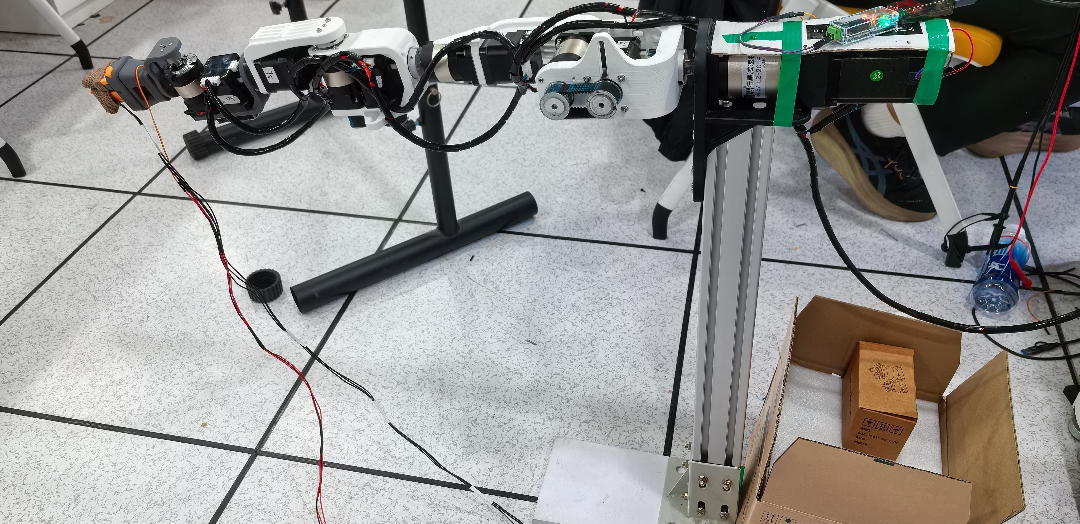
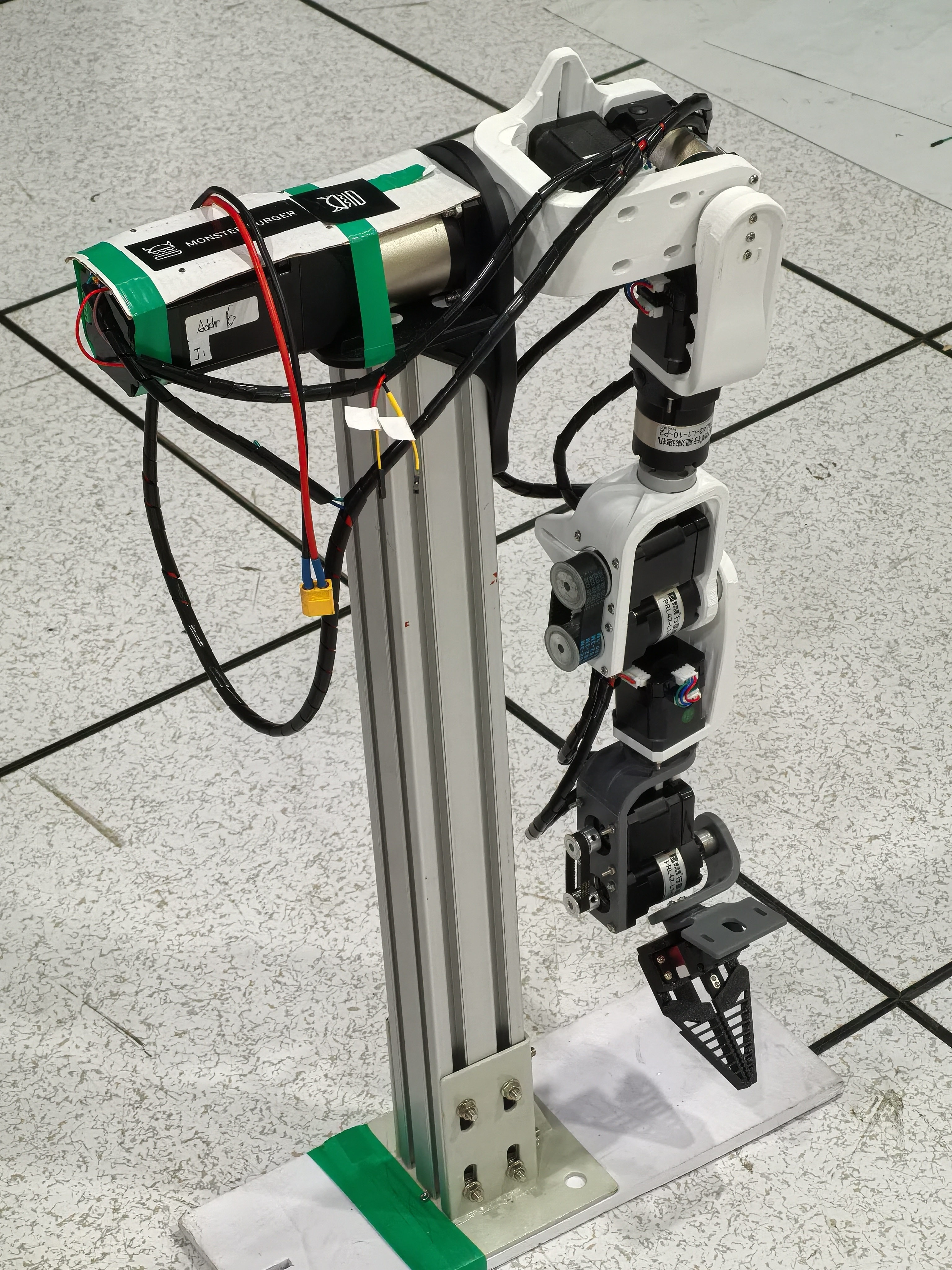
Main features:
| Parameter | Value |
|---|---|
| Arm degrees of freedom | 6 (J1–J6) |
| Reach (including gripper) | Approximately 610mm |
| Target end-effector payload | 350g |
| Control interface | CAN bus / servo signal |
| Power supply | 24VDC (stepper motors) / 5VDC (servo) |
| Structural material | PLA 3D-printed parts |
ArmSync/
├── Hardware/                         # Mechanical, electrical, and assembly resources
│   ├── 3D Files/                     # Robot arm, gripper, and controller 3D models
│   │   ├── 3MF for printing/         # 3MF files ready for slicing
│   │   ├── SolidWorks 2026/          # SolidWorks source files
│   │   ├── STEP and STL/             # STEP/STL universal formats
│   │   └── URDF/                     # ROS/Gazebo model
│   ├── PCBs/                         # PCB projects and images
│   ├── example_imgs/                 # J1–J6 and EE assembly illustrations
│   ├── Parts BOM-zh-CN.md            # Chinese bill of materials
│   ├── Assembly Guide-zh-CN.md       # Chinese assembly guide
│   └── readme-zh-CN.md               # Hardware documentation
├── Software/                         # Firmware, kinematics tools, and UI resources
│   ├── Arm-Side/                     # RA8P1 robot-arm controller project
│   │   ├── Solution/                 # e² studio Solution, CPU0, and CPU1 projects
│   │   ├── arm_ik_test.py            # IK visualization tool for Jetson input
│   │   ├── arm_angle_view.py         # Joint-angle and spatial-vector visualization tool
│   │   └── Scripts README-zh-CN.md   # Python tools usage guide
│   ├── User-Side/                    # RA4M1 user-side controller and IMU projects
│   ├── Deprecated Project Folders/   # Deprecated projects
│   ├── UI/                           # HMI, UI layout, and font resources
│   └── readme-zh-CN.md               # Software documentation
├── Helpful Docs/                     # Reference material for MCU, NPU, HMI, and dual-core development
├── LICENSE
├── README-zh-CN.md
└── README.mdFor printing the mechanical parts, use:
Hardware/3D Files/3MF for printing/Renesas ArmSync.3mf
You can also use the universal models in STEP and STL/ or modify the source files in SolidWorks 2026/.
Read the software documentation to understand the current project structure and toolchains:
Make sure that the FSP, Arm GCC toolchain, serial-port configuration, and actual hardware version are compatible.
| Qty | Value | Footprint | References |
|---|---|---|---|
| 2 | CAN | Connector_JST:JST_GH_SM02B-GHS-TB_1x02-1MP_P1.25mm_Horizontal | CAN, CAN |
| 2 | PWR24 | TerminalBlock_Altech:Altech_AK100_1x02_P5.00mm | 24V, J3 |
| 2 | SERVO_CABLE | Connector_JST:JST_XH_B2B-XH-A_1x02_P2.50mm_Vertical | J7, J8 |
| 1 | LOGO | Renesas Icon:RenesasIcon | G*** |
| 1 | SERVO_OUT | Connector_Molex:Molex_KK-254_AE-6410-03A_1x03_P2.54mm_Vertical | GND 5V SIG |
| 1 | STEPPER_BUS | Connector_PinSocket_2.54mm:PinSocket_1x08_P2.54mm_Vertical | J1 |
It measures 31 × 21.8 mm and has 2 copper layers, 1.6 mm thick.
9 parts. The full list of its parts is on this page, with links to each part's symbol and footprint where PCBKit's library has them.
From the WilliTourt/ArmSync repository on GitHub, at the commit this page was made from: the board is Hardware/PCBs/KiCad 10/Renesas ArmSync CAN Connector/Renesas ArmSync CAN Connector.kicad_pcb and its schematic Hardware/PCBs/KiCad 10/Renesas ArmSync CAN Connector/Renesas ArmSync CAN Connector.kicad_sch. PCBKit opens the board in the browser, with nothing to install.
Its repository publishes it under the MIT licence: you may reuse it on that licence's terms (keep the author's notice, and for a copyleft licence share your changes alike).


FrameworkComputer/ExpansionCards
Reference designs and documentation to create Expansion Cards for the Framework Laptop

VoronDesign/Voron-Hardware
Cool Hardware designed by the Voron Design group

hackclub/OnBoard
💡 Join 1,000 teenagers and make your first PCB with a $100 grant!


adamws/kicad-kbplacer
KiCad plugin for automatic keyboard's key placement and routing