2 layers92 × 92 mm
 WiddleWabbit/MQTT-ModularControllerBoard
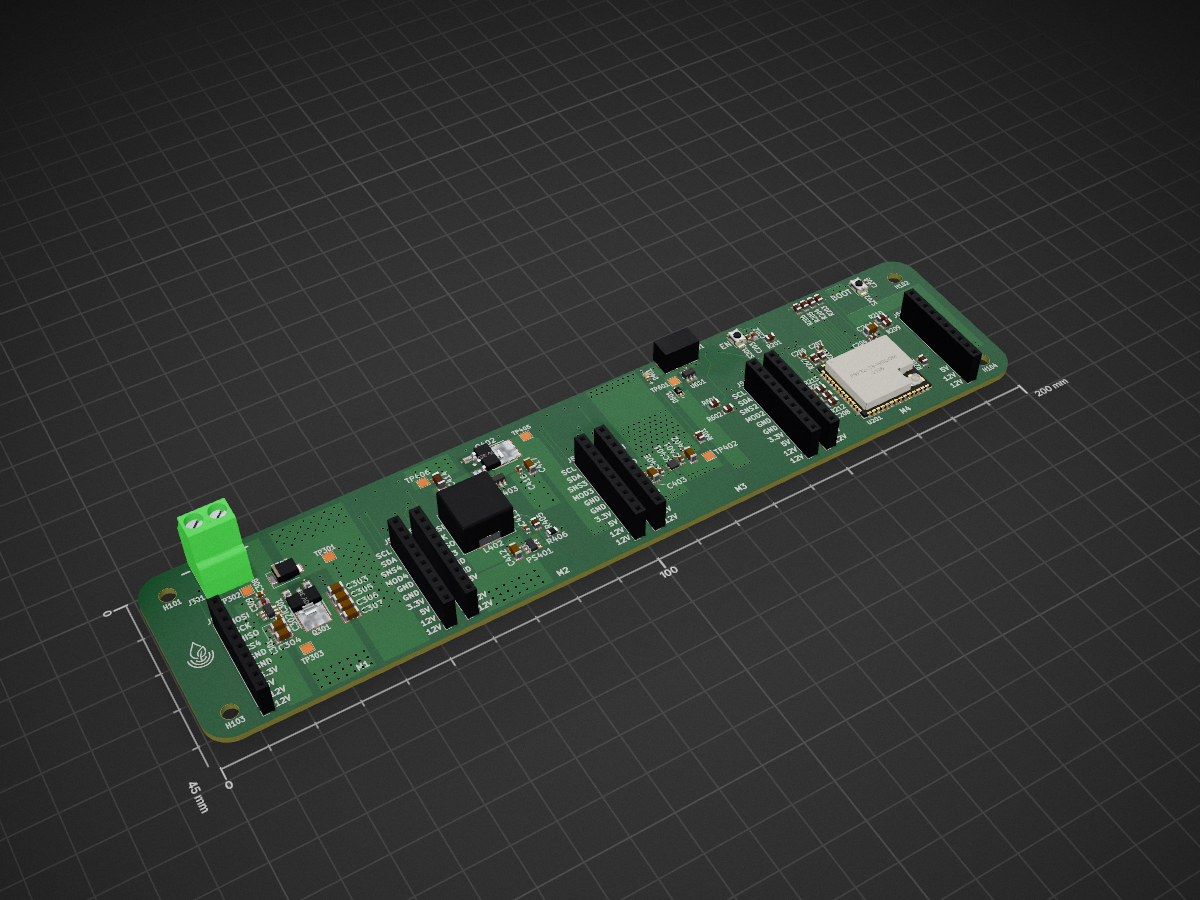
ESP32-S3-WROOM-1U based motherboard designed to communicate externally via MQTT, and read sensors, control interfaces and other hardware through purpose built modules. For example, actuator control (pumps, solenoids, etc.), and water sensor readings etc.
MQTT ModularControllerBoard is an open-source printed circuit board by WiddleWabbit, from the WiddleWabbit/MQTT-ModularControllerBoard repository on GitHub, published under the CERN-OHL-P-2.0 licence. It is a 4-layer board of 200 × 45 mm with 83 parts on 57 nets, routed with 652 tracks and 490 vias.
It is built around the ESP32-S3-WROOM-1U-N16R8, TPS54308DDCR and LM74700QDBVTQ1, with the TLV76733DRVR, A2541HWV-10P and KT-0603R among its other parts. Its parts include 27 capacitors, 18 resistors, 10 connectors, 5 ICs and 3 diodes. It belongs with the home automation and IoT and sensors and measurement boards and the ESP32 boards of this library.


Currently In Testing - Not Yet Tested
ESP32-S3-WROOM-1U based motherboard designed to communicate externally via MQTT, and read sensors, control interfaces and other hardware through purpose built modules. For example, actuator control (pumps, solenoids, etc.), and water sensor readings etc.
Each of the four modules connects via two 10-pin headers and receives:
Slot 1:
Slot 2:
Slot 3:
Slot 4:
4-layer board:
Component/Routing → Ground plane → Ground plane → Routing
Impedance Control: Designed for JLCPCB Impedance Control Stackup of JLC04161H-7628, Finished thickness of 1.59mm.
Firmware: The PlatformIO firmware includes non-blocking WiFi station reconnection and a captive-portal setup flow. On first boot, the portal scans nearby networks and offers a selectable SSID list plus manual SSID entry.
Programming:
Module Development: Modules must conform to the 2x10 header pinout with 40mm pitch. Board uses 2 x 10, 8.5mm Female Headers (A2541HWV-10P). Recommended 3A support.
This documentation is part of MQTT-ModularControllerBoard Project and is licensed under the CERN Open Hardware Licence Version 2 - Permissive (CERN-OHL-P-2.0). You may redistribute and modify this documentation under the terms of the CERN-OHL-P-2.0. This documentation is distributed WITHOUT ANY EXPRESS OR IMPLIED WARRANTY, INCLUDING OF MERCHANTABILITY, SATISFACTORY QUALITY AND FITNESS FOR A PARTICULAR PURPOSE. See the CERN-OHL-P-2.0 for applicable conditions.
| Qty | Value | Footprint | References |
|---|---|---|---|
| 11 | 10uF 10% 25V | JLCPCB Basic:CAPC3216X180N | C201, C302, C303, C304, C305, C306, C307, C402, C405, C412, C417 |
| 9 | 0.1uF 10% 50V | JLCPCB Basic:CAPC1608X90N | C203, C204, C205, C301, C308, C401, C403, C413, C416 |
| 8 | A2541HWV-10P | CJT Connectors:PinSocket_1x10_P2.54mm_Vertical_Female | J501, J502, J503, J504, J505, J506, J507, J508 |
| 8 | TestPoint | TestPoint:TestPoint_Pad_2.0x2.0mm | TP301, TP302, TP303, TP402, TP405, TP406, TP407, TP601 |
| 6 | 10kΩ 1/8W 1% | JLCPCB Basic:RESC2013X65N | R201, R202, R203, R204, R205, R206 |
| 4 | 3.5mm | MountingHole:MountingHole_3.5mm | H101, H102, H103, H104 |
| 3 | 100kΩ 1/8W 1% | JLCPCB Basic:RESC2013X65N | R405, R601, R602 |
| 3 | 22pF 5% 50V | JLCPCB Basic:CAPC1608X90N | C206, C207, C208 |
| 3 | 47Ω 1/8W 1% | JLCPCB Basic:RESC2013X65N | R211, R212, R213 |
| 2 | 220nF 10% 50V | JLCPCB Basic:CAPC2012X135N | C309, C415 |
| 2 | 22Ω 1/8W 5% | JLCPCB Basic:RESC2013X65N | R207, R208 |
| 2 | 4.7kΩ 1/8W 1% | JLCPCB Basic:RESC2013X65N | R209, R210 |
| 2 | 60V 38A | ONSEMI Transistors:DPAK__SINGLE-GAUGE__TO-252_369C__ISSUE_F | Q301, Q402 |
| 2 | LM74700QDBVTQ1 | TEXAS INSTRUMENTS ICs:SOT95P280X145-6N | IC301, IC403 |
| 2 | LOGO | LOGO | G***, G*** |
| 2 | Push Button SPST | JLCPCB Basic:SW_TS-1088-AR02016 | S201, S202 |
| 1 | 1051640001 | MOLEX Connectors:CON00906_5_MOL | J601 |
| 1 | 10uH, 5.4A, 20% | Inductor_SMD:L_SXN_SMDRI127 | L402 |
| 1 | 13.7kΩ 1/8W 1% | YAGEO Resistors:RESC2012X60N | R406 |
| 1 | 13V 21.5V 1uA Leak | LITTELFUSE Diodes:DO-214AA_Bidirectional | D303 |
| 1 | 1715721 | PHOENIX CONTACT Terminals:1715721 | J301 |
| 1 | 1uF 10% 50V | JLCPCB Basic:CAPC2012X135N | C202 |
| 1 | 330Ω 1/8W 1% | JLCPCB Basic:RESC2013X65N | R401 |
| 1 | 40V 1A | GUANGDONG HOTTECH Diodes:D_SOD-323F | D601 |
| 1 | 47uF 20% 10V | JLCPCB Basic:CAPC3216X190N | C414 |
| 1 | ESD Protection IC | STMICROELECTRONICS Protection:SOT95P280X145-6N | U601 |
| 1 | ESP32-S3-WROOM-1U-N16R8 | ESPRESSIF Microcontrollers:ESP32-S3-WROOM-1U | U201 |
| 1 | KT-0603R | JLCPCB Basic:LED_0603_1608Metric | D401 |
| 1 | TLV76733DRVR | TEXAS INSTRUMENTS ICs:SON65P200X200X80-7N | IC401 |
| 1 | TPS54308DDCR | TEXAS INSTRUMENTS ICs:SOT95P280X110-6N | PS401 |
It measures 200 × 45 mm and has 4 copper layers, 1.6 mm thick.
83 parts, built around the ESP32-S3-WROOM-1U-N16R8, TPS54308DDCR, LM74700QDBVTQ1 and TLV76733DRVR. The full list of its parts is on this page, with links to each part's symbol and footprint where PCBKit's library has them.
From the WiddleWabbit/MQTT-ModularControllerBoard repository on GitHub, at the commit this page was made from: the board is MQTT-ModularControllerBoard.kicad_pcb and its schematic ESP32-S3-WROOM-1U.kicad_sch. PCBKit opens the board in the browser, with nothing to install.
Its repository publishes it under the CERN-OHL-P-2.0 licence: you may reuse it on that licence's terms (keep the author's notice, and for a copyleft licence share your changes alike).


Thornbots/Electrical
Here is where we store all relevant files for the Electrical team. In here you will store all of the KiCad files that you produce through out the year.

kenchangh/kensat
KENSAT, Edge-AI Compute in Orbit - A 2U CubeSat that runs a large language model on-orbit. A power-gated NVIDIA Jetson Orin Nano executes neural-network inference in space, and the results are downlinked over a custom…


danbrunski/canary
Four 25 F cells in series for CANary-PWR's LTC3350 hold-up, on a lead (design record: docs/CANary-PWR-Spec.md §P4). The board has no active parts: four cells, an NTC, two Kelvin net ties and a Micro-Fit 2 × 5 header.