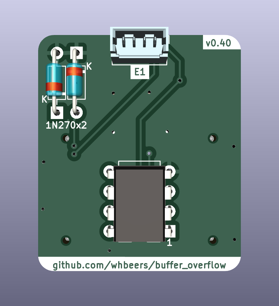
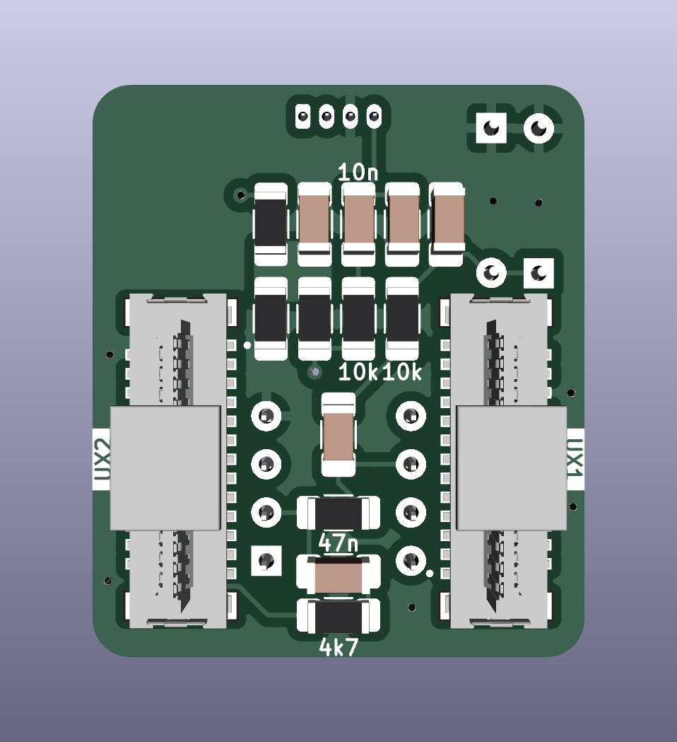
2 layers43.9 × 27.7 mm
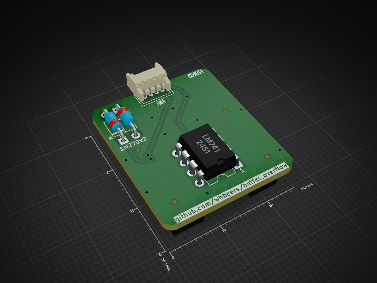
 whbeers/buffer_overflow4
pcb design for overdrive effect based on DOD Overdrive 250
Buffer overflow is an open-source printed circuit board by whbeers, from the whbeers/buffer_overflow repository on GitHub, published under the CC0-1.0 licence. It is a 2-layer board of 25.9 × 30.1 mm with 19 parts on 56 nets, routed with 55 tracks and 15 vias.
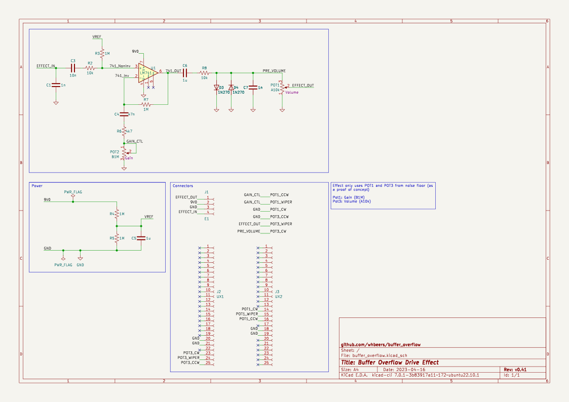
Its parts include 7 resistors, 6 capacitors, 3 connectors, 2 diodes and 1 IC.
This is a re-creation of the DOD Overdrive 250 / MXR Distortion+ op-amp drive circuit, as a first attempt at basic PCB design in KiCAD.
The board is built on the "Noise Floor" pedal platform, which provides basic power protection, audio IO, and a footswitch with LED indicator.
The basic schematic I worked from is available from a variety of sources, but this was primarily derived from the PedalPCB Distortion 250. I strongly endorse PedalPCB (and this pedal) as a great way to get started building effects.
Thanks as always to the folks on the freestompboxes.org forum for feedback and suggestions.
Conan Lite footprints adapted from the 51-position footprints available from SnapEDA: Header, Receptacle.(Additional license details). 3D models courtesy Amphenol.
I am not affiliated with any of the brands, sites, or products named in this overview.
My pcb designs utilize the following versioning scheme (I'll add to this as I produce more revisions):
v0.40 updates Buffer Overflow as a proof-of-concept for the experimental Noise Floor UX board, which uses board-to-board connectors to modularize the control surface the effect. While it only exercises two potentiometers from the UX board, I may expand use of it (e.g. switchable clipping diode banks, etc).
I've also changed resistors and capacitors to 1206 SMD parts. Due to the fact that the board-to-board assemblies are also surface mount, it meant moving almost all parts to the back of the board. This resulted in an awkward-looking layout, to say the least, and I expect it to evolve over time.
The name "Buffer Overflow" is a reflection of the nature of the effect (an overdrive) and security nerdery.
| Qty | Value | Footprint | References |
|---|---|---|---|
| 4 | 1M | Resistor_SMD:R_1206_3216Metric_Pad1.30x1.75mm_HandSolder | R3, R4, R5, R7 |
| 2 | 10k | Resistor_SMD:R_1206_3216Metric_Pad1.30x1.75mm_HandSolder | R2, R8 |
| 2 | 1N270 | Diode_THT:D_DO-35_SOD27_P7.62mm_Horizontal | D3, D4 |
| 2 | 1n | Capacitor_SMD:C_1206_3216Metric_Pad1.33x1.80mm_HandSolder | C1, C7 |
| 2 | 1u | Capacitor_SMD:C_1206_3216Metric_Pad1.33x1.80mm_HandSolder | C5, C6 |
| 1 | 10n | Capacitor_SMD:C_1206_3216Metric_Pad1.33x1.80mm_HandSolder | C3 |
| 1 | 47n | Capacitor_SMD:C_1206_3216Metric_Pad1.33x1.80mm_HandSolder | C4 |
| 1 | 4k7 | Resistor_SMD:R_1206_3216Metric_Pad1.30x1.75mm_HandSolder | R6 |
| 1 | E1 | buffer_overflow:Molex_PicoBlade_53047-0410_1x04_P1.25mm_Vertical_with_3D_Model | J1 |
| 1 | LM741 | Package_DIP:DIP-8_W7.62mm | U1 |
| 1 | UX1 | buffer_overflow:Amphenol_Header_25Pin_10162582-1134125LF | J2 |
| 1 | UX2 | buffer_overflow:Amphenol_Header_25Pin_10162582-1134125LF | J3 |
It measures 25.9 × 30.1 mm and has 2 copper layers, 1.6 mm thick.
19 parts. The full list of its parts is on this page, with links to each part's symbol and footprint where PCBKit's library has them.
From the whbeers/buffer_overflow repository on GitHub, at the commit this page was made from: the board is hardware/buffer_overflow.kicad_pcb and its schematic hardware/buffer_overflow.kicad_sch. PCBKit opens the board in the browser, with nothing to install.
Its repository publishes it under the CC0-1.0 licence: you may reuse it on that licence's terms (keep the author's notice, and for a copyleft licence share your changes alike).

hackclub/OnBoard
💡 Join 1,000 teenagers and make your first PCB with a $100 grant!

polpo/picogus
Emulation of ISA sound cards and CD-ROM on Raspberry Pi Pico (GUS, SB/Adlib, MPU-401, Tandy, CMS, Panasonic CD-ROM) with USB mouse/joystick support


nkitanov/iaq_board
IAQ Board is a DIY (Do-It-Yourself) device for measuring internal air quality


Ardumower/ardumower
Develop an open source robotic lawn mower (HW+SW reference platform)

zmaker/arduino_cookbook
gli sketch del nuovo progetto Arduino Cookbook e dei video di YouTube