4 layers65 × 30 mm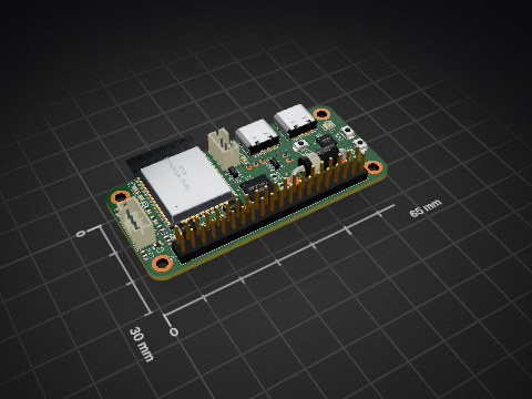

 wafleee/Mini-RP2040-Devboard
I made a mini devboard that uses the RP2040 as the MCU. It is slightly bigger than the XIAO esp32 s3 but it features 4 extra pins
Mini RP2040-Devboard is an open-source printed circuit board by wafleee, from the wafleee/Mini-RP2040-Devboard repository on GitHub. It is a 4-layer board of 22.8 × 25.7 mm with 34 parts on 59 nets, routed with 761 tracks and 113 vias.
It is built around the RP2040, W25Q128JVSIQ and AP2112K-3.3, with the USBLC6-2SC6 and WS2812B-2020 among its other parts. Its parts include 17 capacitors, 6 resistors, 4 ICs, 3 connectors and 2 diodes. It belongs with the microcontroller boards boards and the RP2040 boards of this library.


No firmware is needed, just hit upload to any sketch on Arduino IDE and it will built itself.
| Designator | Footprint | Qty | Value | Link |
|---|---|---|---|---|
| C10, C12, C13, C14, C15, C16, C17, C19, C3, C9 | 603 | 10 | 100nF | Already owned |
| C11, C18, C7, C8 | 603 | 4 | 1µF | Robu |
| C4, C5 | 603 | 2 | 15pF | Robu |
| C6 | 805 | 1 | 10µF | Robu |
| D1 | LED_WS2812B-2020_PLCC4_2.0x2.0mm | 1 | WS2812B-2020 | Robu |
| D2 | 603 | 1 | LED | Robu |
| J1 | USB_C_Receptacle_GCT_USB4105-xx-A_16P_TopMnt_Horizontal | 1 | USB_C_Receptacle_USB2.0_14P | Robu |
| J4, J5 | PinHeader_1x10_P2.54mm_Vertical | 2 | Conn_01x10_Pin | Robu |
| R1, R2 | 603 | 2 | 5.1kΩ | Robu |
| R3, R6 | 603 | 2 | 1kΩ | Robu |
| R4, R5 | 603 | 2 | 27Ω | Robu |
| SW1 | SW_SPST_B3U-1000P | 1 | SW_MEC_5G | Robu |
| U1 | QFN-56-1EP_7x7mm_P0.4mm_EP3.2x3.2mm | 1 | RP2040 | Robu |
| U3 | SOIC-8_5.3x5.3mm_P1.27mm | 1 | W25Q128JVS | Lion Circuits |
| U4 | SOT-23-5 | 1 | AP2112K-3.3 | Lion Circuits |
| U5 | SOT-23-6 | 1 | USBLC6-2SC6 | Robu |
| Y2 | Crystal_SMD_Abracon_ABM8AIG-4Pin_3.2x2.5mm | 1 | Crystal_GND3 | Robu |
Kicad - https://www.kicad.org/
| Qty | Value | Footprint | References |
|---|---|---|---|
| 10 | 100nF | Capacitor_SMD:C_0603_1608Metric | C3, C9, C10, C12, C13, C14, C15, C16, C17, C19 |
| 4 | 1uF | Capacitor_SMD:C_0603_1608Metric | C7, C8, C11, C18 |
| 2 | 15pF | Capacitor_SMD:C_0603_1608Metric | C4, C5 |
| 2 | 1k | Resistor_SMD:R_0603_1608Metric | R3, R6 |
| 2 | 27 | Resistor_SMD:R_0603_1608Metric | R4, R5 |
| 2 | 5.1k | Resistor_SMD:R_0603_1608Metric | R1, R2 |
| 2 | Conn_01x10_Pin | Connector_PinHeader_2.54mm:PinHeader_1x10_P2.54mm_Vertical | J4, J5 |
| 1 | 10uF | Capacitor_SMD:C_0805_2012Metric | C6 |
| 1 | AP2112K-3.3 | Package_TO_SOT_SMD:SOT-23-5 | U4 |
| 1 | Crystal_GND3 | Crystal:Crystal_SMD_Abracon_ABM10-4Pin_2.5x2.0mm | Y2 |
| 1 | LED | LED_SMD:LED_0603_1608Metric | D2 |
| 1 | RP2040 | Package_DFN_QFN:QFN-56-1EP_7x7mm_P0.4mm_EP3.2x3.2mm | U1 |
| 1 | SW_MEC_5G | Button_Switch_SMD:SW_SPST_B3U-1000P | SW1 |
| 1 | USBLC6-2SC6 | Package_TO_SOT_SMD:SOT-23-6 | U5 |
| 1 | USB_C_Receptacle_USB2.0_14P | Connector_USB:USB_C_Receptacle_GCT_USB4105-xx-A_16P_TopMnt_Horizontal | J1 |
| 1 | W25Q128JVS | Package_SO:SOIC-8_5.3x5.3mm_P1.27mm | U3 |
| 1 | WS2812B-2020 | LED_SMD:LED_WS2812B-2020_PLCC4_2.0x2.0mm | D1 |
It measures 22.8 × 25.7 mm and has 4 copper layers, 1.6 mm thick.
34 parts, built around the RP2040, W25Q128JVSIQ, AP2112K-3.3 and USBLC6-2SC6. The full list of its parts is on this page, with links to each part's symbol and footprint where PCBKit's library has them.
From the wafleee/Mini-RP2040-Devboard repository on GitHub, at the commit this page was made from: the board is PCB/Mini RP2040 Devboard.kicad_pcb and its schematic PCB/Mini RP2040 Devboard.kicad_sch. PCBKit opens the board in the browser, with nothing to install.
Its repository states no licence, so its author keeps all rights: ask wafleee before reusing the design.

flavioamieiro/leme-macropad
This is a macropad based on the RP2040 microcontroller meant to run QMK.

yuz207/agentpad13
agentpad13 — open-source 13-key macropad for agentic work (RP2040, vial-qmk, planar joystick, Raw HID agent-status protocol)

Isaac-Duarte/wellfed
Open firmware that runs the PETLIBRO Granary PLAF103 pet feeder on your own Wi-Fi: no cloud, no account. Early and in testing.

BlackPancakes/RP2040-Logic-Analyzer
An open-source, high-speed, multi-channel logic analyzer based on the popular Raspberry Pi RP2040 microcontroller. The board was designed in KiCad with a strong focus on signal integrity and miniaturization.

0x0c/spltnrskb
KLE レイアウト(kle/left.json、kle/right.json)から生成した、左右分割・有線接続のキーボード基板です。 KiCad 10 のプロジェクト(回路図と配線済み基板)、製造用ガーバー、BOM、QMK ファームウェア設定を含みます。筐体のデータ(アクリルのレーザーカット用 DXF/SVG と 3D プリント用 STL)も入っています。

Vishalbabu-09/Auralab_Workstation
Advanced 4-layer PCB design featuring split-plane noise isolation (AGND/DGND) and asynchronous dual-core processing. Implements a handheld multi-tool oscilloscope, current tracker, and symmetrical DC power supply.

jadenrhee/wigglecam-controller
RP2040 co-processor board for a 4-lens wigglegram camera: constant-current flash, controls, battery telemetry, Pi 5 I2C interface. 4-layer, DRC-clean, fab-ready.