
2 layers327.9 × 139 mm
Coco2
baldengineer/bit-preserve
Project for capturing vintage, classic, aka old computer schematics in KiCad.
147 parts446

 VulcanWM/helios
blinky board
Helios is an open-source printed circuit board by VulcanWM, from the VulcanWM/helios repository on GitHub. It is a 2-layer board of 30.4 × 10.1 mm with 23 parts on 18 nets, routed with 127 tracks and 15 vias.
It is built around the NE555P. Its parts include 10 diodes, 2 capacitors, 2 resistors, 2 ICs and 1 connector.
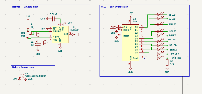
Helios is a circular LED chaser PCB built using an NE555 timer and CD4017 decade counter. Ten LEDs are arranged around the outside of the board and light up one after another, creating a rotating light effect.
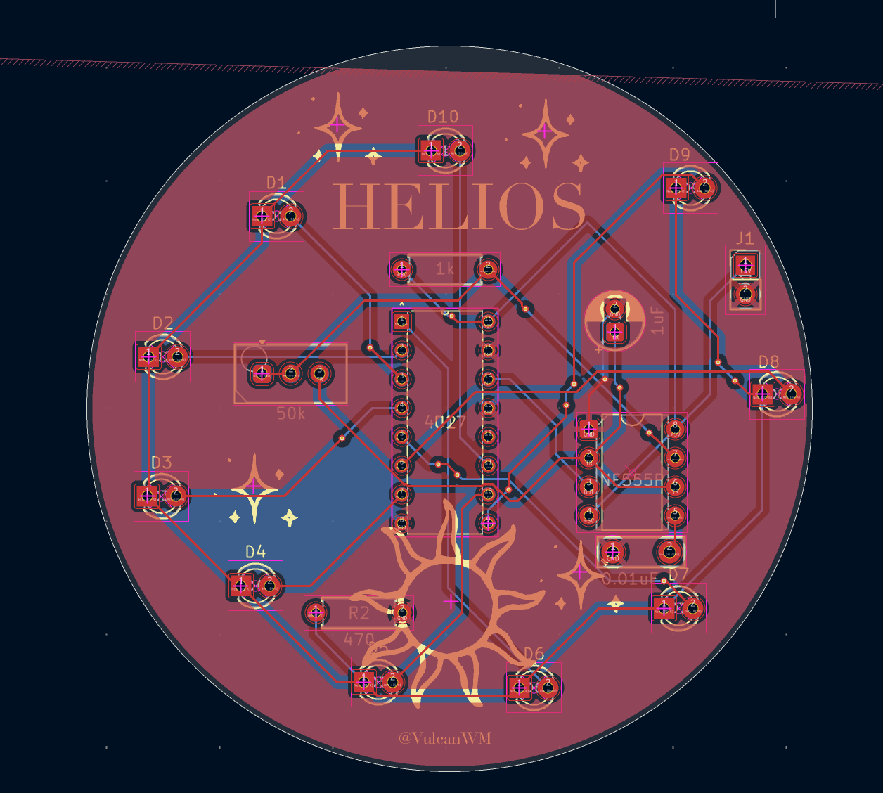
The PCB was designed in KiCad and uses a circular layout with custom Helios-themed silkscreen artwork.
The NE555 timer is configured in astable mode, meaning it continuously generates electrical pulses without requiring an external trigger.
A 50k potentiometer controls the timing of these pulses, allowing the speed of the LED sequence to be adjusted.
The output of the NE555 is connected to the clock input of a CD4017 decade counter. Every time the CD4017 receives a pulse, it advances its active output by one:
Each of the ten outputs is connected to one of the ten LEDs positioned around the edge of the PCB. This makes the illuminated LED appear to travel around the circular board.
A 470 ohm resistor limits the current flowing through the LEDs, while the circuit is powered through a 5V connection.
Turning the potentiometer changes the frequency of the pulses generated by the NE555, so the LEDs can chase around the board faster or slower.
This repository contains all the hardware files you would need to replicate this project. Everything was done in KiCad.
The pcb folder contains the KiCad source files (.kicad_sch, .kicad_pro, .kicad_pcb) and the gerbers.zip which was used to manufacture the PCB.
This is what the schematic looks like:
This is what the PCB looks like:
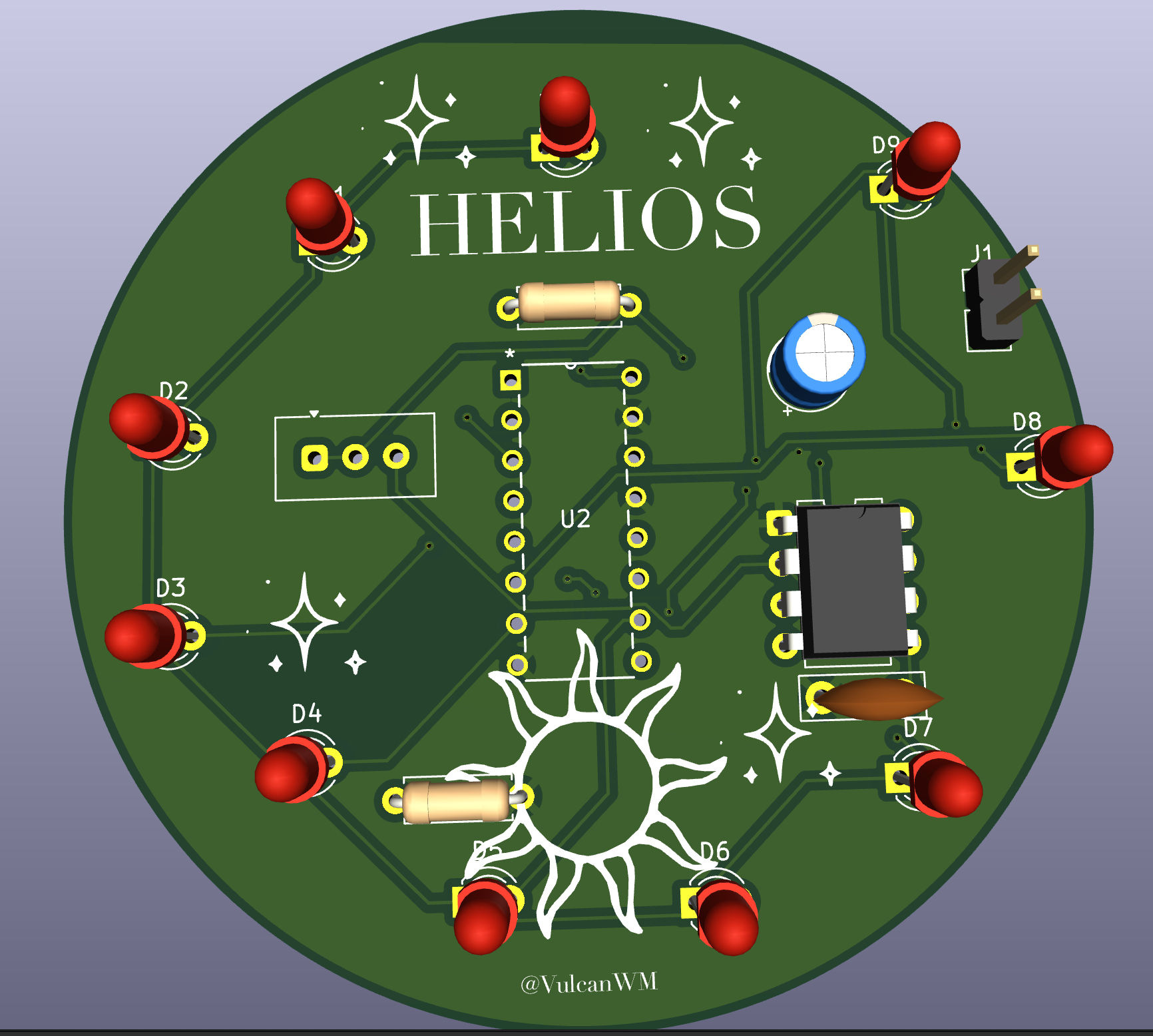
This is what the PCB looks like in 3D:
Also in the BOM.csv file.
| Name | Quantity | Link To Buy | Cost (USD) |
|---|---|---|---|
| NE555P Timer IC | 1 | LCSC | $1.34 for 5 |
| CD4017 Decade Counter IC | 1 | LCSC | $0.60 for 5 |
| 5 mm LED | 10 | LCSC | $0.57 for 20 |
| Vishay T93YA 50 kΩ Potentiometer | 1 | LCSC | $3.43 |
| 1 kΩ Through-Hole Resistor | 1 | LCSC | $1.10 for 50 |
| 470 Ω Through-Hole Resistor | 1 | LCSC | $0.79 for 100 |
| 10 nF Ceramic Capacitor | 1 | LCSC | $0.99 for 50 |
| 1 uF Electrolytic Capacitor | 1 | LCSC | $0.51 for 5 |
| 2-pin 2.54 mm Male Pin Header | 1 | LCSC | $0.91 for 50 |
| Total | $10.24 |
| Qty | Value | Footprint | References |
|---|---|---|---|
| 10 | LED | LED_THT:LED_D3.0mm | D1, D2, D3, D4, D5, D6, D7, D8, D9, D10 |
| 5 | LOGO | LOGO | G***, G***, G***, G***, G*** |
| 1 | 0.01uF | Capacitor_THT:C_Disc_D7.5mm_W2.5mm_P5.00mm | C1 |
| 1 | 1k | Resistor_THT:R_Axial_DIN0207_L6.3mm_D2.5mm_P7.62mm_Horizontal | R1 |
| 1 | 1uF | Capacitor_THT:CP_Radial_D5.0mm_P2.00mm | C2 |
| 1 | 4017 | footprints:N16 | U2 |
| 1 | 470 | Resistor_THT:R_Axial_DIN0207_L6.3mm_D2.5mm_P7.62mm_Horizontal | R2 |
| 1 | 50k | Potentiometer_THT:Potentiometer_Vishay_T93YA_Vertical | RV1 |
| 1 | Conn_01x02_Socket | Connector_PinHeader_2.54mm:PinHeader_1x02_P2.54mm_Vertical | J1 |
| 1 | NE555P | Package_DIP:DIP-8_W7.62mm | U1 |
baldengineer/bit-preserve
Project for capturing vintage, classic, aka old computer schematics in KiCad.

The-Invent0r/8-bit-Computer-PCB
These are the KiCAD files for my 8-Bit Computer.

DarcyJProjects/touchtone555
An open-source DIY, NE555-based analogue synthesizer - play notes with a stylus


benjiaomodular/SynthCard
I designed this project with the help of PCBWay. You can get a copy of these cards through the PCBWay Shared Projects page.

fortinsylvain/MyCpu
Home brew CPU Hardware with 1-bit ALU implementation using 74LSxx, a micro-code and assembler coded in C#.

hackup/C128Diag
Replica of the Commodore C128 Diagnostic Test cartridge Assy No. 325093-01.
It measures 30.4 × 10.1 mm and has 2 copper layers, 1.6 mm thick.
23 parts, built around the NE555P. The full list of its parts is on this page, with links to each part's symbol and footprint where PCBKit's library has them.
From the VulcanWM/helios repository on GitHub, at the commit this page was made from: the board is pcb/helios.kicad_pcb and its schematic pcb/helios.kicad_sch. PCBKit opens the board in the browser, with nothing to install.
Its repository states no licence, so its author keeps all rights: ask VulcanWM before reusing the design.