2 layers82 × 54.5 mm

 vlkv/chocofly75
Ergonomic monosplit keyboard on kailh choc switches
Chocofly fz is an open-source printed circuit board by vlkv, from the vlkv/chocofly repository on GitHub, published under the MIT licence. It is a 2-layer board of 304 × 133.5 mm with 134 parts on 91 nets, routed with 1,431 tracks and 69 vias.
Its parts include 63 switches, 62 diodes and 2 connectors. It belongs with the keyboards and input boards and the AVR (ATmega, ATtiny) boards of this library.
The Chocofly is an ergonomic monosplit keyboard with 4x6 column staggered keys, 4 thumb keys and 2 additional inner keys for the index finger (60 keys total) plus one rotary encoder.
The main idea of the Chocofly is to be thin and suitable for "sonshi"-style usage (putting it ontop the laptop keyboard). It is also pretty minimalistic - no LEDs/OLEDs/labels on keycaps/wires... and in my build it even has no case. It's just a pcb with switches on top of it and small silicone legs on the bottom. And this setup works pefectly! Well, for me at least.
Notable features:
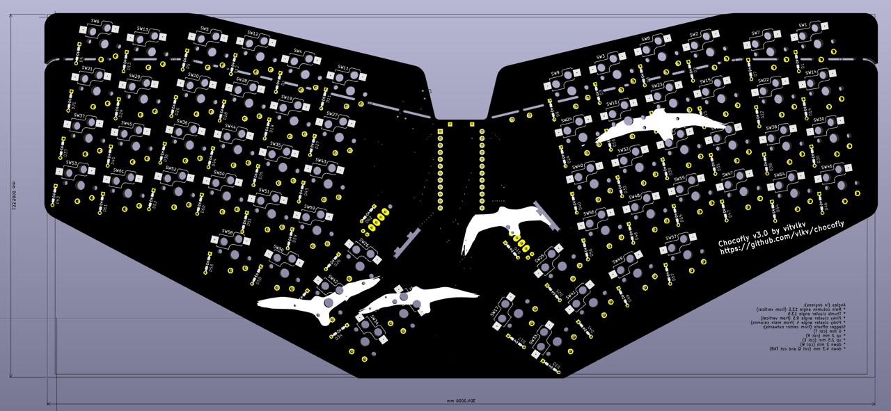 Chocofly v3 PCB.
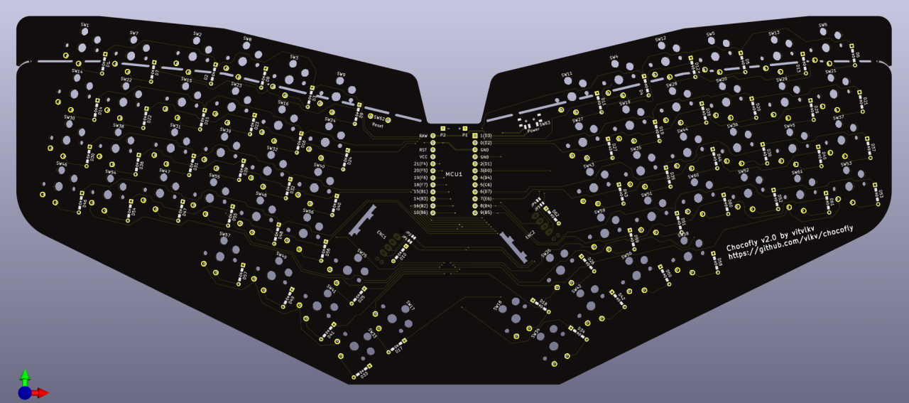 Chocofly v2 PCB.
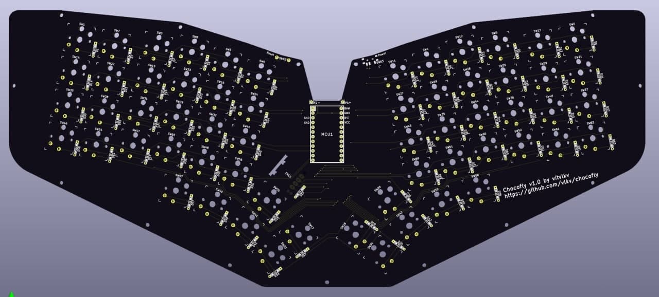 Chocofly v1 PCB.
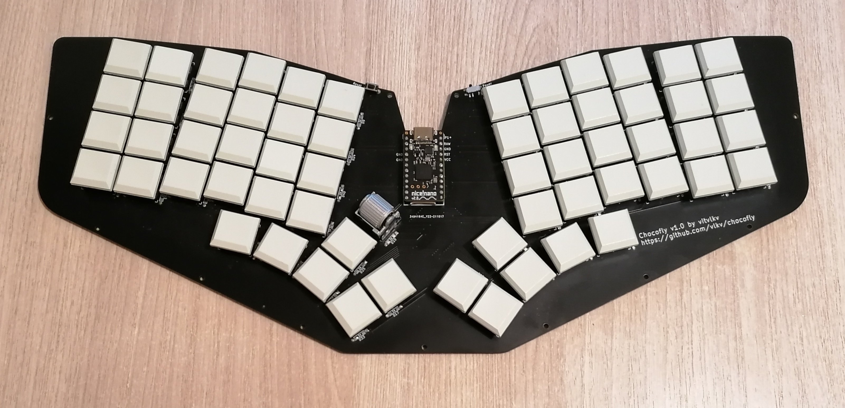 Chocofly v1.
TODO.
Is here.
See similar https://github.com/vlkv/avalanche#build-instructions
A few tips specific to the Chocofly:
There is a chat group in Telegram, where you may chat about the project or ask some questions/help.
| Qty | Value | Footprint | References |
|---|---|---|---|
| 62 | 1N4148 | footprints:diode_TH_SMD | D1, D2, D10, D11, D12, D13, D14, D15, D16, D17, D18, D19, D20, D21, D22, D23 +46 |
| 60 | SW_Push | footprints:Kailh_socket_PG1350_chosfox_17_5mm | SW1, SW2, SW11, SW12, SW13, SW14, SW15, SW16, SW17, SW18, SW19, SW20, SW21, SW22, SW23, SW24 +44 |
| 2 | EVQWGD001 | footprints:EVQWGD001 | ENC1, ENC2 |
| 2 | Jumper_NC_Small | footprints:avalanche_Jumper | JP3, JP4 |
| 2 | Jumper_NC_Small | footprints:avalanche_Jumper_NC | JP1, JP2 |
| 2 | Power | footprints:Switch_MSK-12C01-07 | SW63, SW64 |
| 1 | ProMicro | footprints:ProMicro | MCU1 |
| 1 | Reset | footprints:Switch_Reset_THT | SW62 |
| 1 | battery+ | footprints:1pin_conn | P1 |
| 1 | battery- | footprints:1pin_conn | P2 |
It measures 304 × 133.5 mm and has 2 copper layers, 1.6 mm thick.
134 parts. The full list of its parts is on this page, with links to each part's symbol and footprint where PCBKit's library has them.
From the vlkv/chocofly repository on GitHub, at the commit this page was made from: the board is pcb/chocofly_fz.kicad_pcb and its schematic pcb/chocofly.kicad_sch. PCBKit opens the board in the browser, with nothing to install.
Its repository publishes it under the MIT licence: you may reuse it on that licence's terms (keep the author's notice, and for a copyleft licence share your changes alike).


ThomasVDD/SmartSupply
SmartSupply is a digital battery powered lab powersupply. It is Arduino compatible and can be controlled via PC over USB.


richardeoin/ax
This repository contains hardware and software for the AX5043 and AX5243 radios from AxSemi (now ON Semiconductor). They are probably the same die, but the AX5243 has fewer pins.
