4 layers95.9 × 90.2 mm
CDH PCB
ManSEDS-Satellites-and-Space-Systems/CubeSat-OBC
The version 2 of the C&DH PCB. Features an STM32H743ZGT6 as central proccessor and 32MB of SDRAM.
95 parts
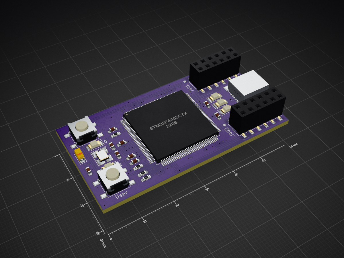
 VladisM/stlinux2
Board for messing around MMU less variant of Linux
Stlinux is an open-source printed circuit board by VladisM, from the VladisM/stlinux repository on GitHub, published under the WTFPL licence. It is a 4-layer board of 59 × 31 mm with 80 parts on 141 nets, routed with 1,254 tracks and 163 vias.
It is built around the FT230XQ-R, IS25LP064A-JBLE and 24LC08B/P, with the IS42S16160J-6TL among its other parts. Its parts include 38 capacitors, 21 resistors, 6 ICs, 5 diodes and 4 connectors. It belongs with the computers and single-board computers boards and the STM32 boards of this library.


Simple board with STM32F446 and SDRAM that is capable of running MMU less linux build. Purpose of this project is to learn new stuffs. It may seems like good thing to have Linux in such small form factor but it isn't. MMU is somehow important in security and using this approach to build device that will be connected to the network is a bad idea.
This project using submodules. After clone use following to init them.
$ git submodule update --init --recursiveGerber files required for manufacturing are stored in board/ger subdirectory.
To manufacture board you shall just find yourself a suitable manufacturer
and use latest archive.
To generate BOM you shall use KiCad and revisit folder board/kicad. All
project files are stored there.
After soldering board you should apply ftdi configuration into
integrated UART bridge. Correct configuration is provided
by the file board/ftdi_configuration.xml. For that you are going
to need Windows PC and FT_PROG tool (available on their website).
To test if board was correctly manufactured and most importantly
assembled. You can use firmware available in board_test folder.
Compile and load firmware, connect using serial port at speed of 115200 and follow instructions.
Warning: at this moment SDIO and SD Card slot test are not implemented!
Everything is compiled using clfs.sh script in root folder of this project. So, if you want to compile whole system simply call following command. (note, adjust number of cores for compilation using -j)
$ ./clfs.sh --build all -j 8After some time, you can find all output images in build/images/. There are:
Bootloader shall be loaded to the board using STLink, and shall be written to the internal Flash memory of MCU.
st-flash write build/images/u-boot.bin 0x08000000Other components are by default loaded from QSPI Flash, there are two ways how to get them there.
This method was used for first revision of board with nonworking SD card slot. If you have second revision of board, use SD card, it is much more faster.
Once you are in u-boot console, you can use xmodem protocol to send all files and then write them to the QSPI Flash. For writing there is mtd command. Follow next code snippet.
> loadx
# send kernel file (zImage) using your console emulator
> mtd erase kernel
> mtd write kernel ${loadaddr}
> loadx
# send rootfs file (clfs.uImage) using your console emulator
> mtd erase rootfs
> mtd write rootfs ${loadaddr}
> loadx
# send dtb file (stm32f446-stlinux.dtb) using your console emulator
> mtd erase rootfs
> mtd write rootfs ${loadaddr}
Then you can simply reset the board or type run bootcmd and you should be
welcomed by kernel boot log.
Compared to using serial port, this one is much much faster because data are transferred over SD card, not xmodem at 115200 bauds.
Create one partition on your SD card, format it as FAT32, and copy there image files from build directory. Then insert your card to the board and run following commands.
> fatload mmc 0:1 ${loadaddr} zImage
> mtd erase kernel
> mtd write kernel ${loadaddr}
> fatload mmc 0:1 ${loadaddr} clfs.uImage
> mtd erase rootfs
> mtd write rootfs ${loadaddr}
> fatload mmc 0:1 ${loadaddr} stm32f446-stlinux.dtb
> mtd erase dtb
> mtd write dtb ${loadaddr}
After reset, your board will boot from QSPI Flash or you can simply type
run bootcmd.
If you are feeling lazy, just copypaste this to bootloader console. And it will boot.
fatload mmc 0:1 ${kernel_addr_l} zImage ; fatload mmc 0:1 ${rootfs_addr_l} clfs.uImage ; fatload mmc 0:1 ${dtb_addr_l} stm32f446-stlinux.dtb ; run set_args ; bootz ${kernel_addr_l} ${rootfs_addr_l} ${dtb_addr_l}It will load everything from SD card into RAM and boot kernel that way.
This project is using a lot of software components that are licensed under various licenses. Always make sure to check what component are you working with to prevent any misunderstanding.
Board manufacturing files, firmware for testing, and build script is licensed using the Do What The Fuck You Want To Public License, Version 2, as published by Sam Hocevar. See COPYING file for more details.
Note: CLFS is abbreviation from Cross Linux From Scratch, in general describing process of cross compiling Linux From Scratch. Please also see CLFS project. My work is influenced by these projects and I learned from their materials a lot.
| Qty | Value | Footprint | References |
|---|---|---|---|
| 29 | 100n | Capacitor_SMD:C_0603_1608Metric_Pad1.08x0.95mm_HandSolder | C201, C202, C205, C208, C209, C210, C211, C212, C213, C214, C215, C216, C217, C218, C301, C302 +13 |
| 5 | 10k | Resistor_SMD:R_0603_1608Metric_Pad0.98x0.95mm_HandSolder | R401, R402, R403, R502, R505 |
| 5 | 330 | Resistor_SMD:R_0603_1608Metric_Pad0.98x0.95mm_HandSolder | R404, R405, R506, R507, R601 |
| 5 | 47k | Resistor_SMD:R_0603_1608Metric_Pad0.98x0.95mm_HandSolder | R301, R302, R303, R304, R305 |
| 5 | LED | LED_SMD:LED_1206_3216Metric_Pad1.42x1.75mm_HandSolder | D401, D402, D501, D502, D601 |
| 4 | 4k7 | Resistor_SMD:R_0603_1608Metric_Pad0.98x0.95mm_HandSolder | R306, R307, R308, R501 |
| 3 | 10u | Capacitor_Tantalum_SMD:CP_EIA-3216-18_Kemet-A_Pad1.58x1.35mm_HandSolder | C304, C601, C603 |
| 2 | 22p | Capacitor_SMD:C_0603_1608Metric_Pad1.08x0.95mm_HandSolder | C204, C207 |
| 2 | 27 | Resistor_SMD:R_0603_1608Metric_Pad0.98x0.95mm_HandSolder | R503, R504 |
| 2 | 2u2 | Capacitor_SMD:C_0603_1608Metric_Pad1.08x0.95mm_HandSolder | C203, C206 |
| 2 | 47p | Capacitor_SMD:C_0603_1608Metric_Pad1.08x0.95mm_HandSolder | C501, C502 |
| 2 | Extension | Connector_PinSocket_2.54mm:PinSocket_2x06_P2.54mm_Vertical_SMD | J401, J402 |
| 1 | 24LC08 | Package_SO:SOP-8_3.9x4.9mm_P1.27mm | U301 |
| 1 | Bus/Self | Jumper:SolderJumper-3_P1.3mm_Open_RoundedPad1.0x1.5mm_NumberLabels | JP501 |
| 1 | Crystal_GND24 | Crystal:Crystal_SMD_3225-4Pin_3.2x2.5mm_HandSoldering | Y201 |
| 1 | FT230XQ | Package_DFN_QFN:QFN-16-1EP_4x4mm_P0.65mm_EP2.1x2.1mm | U501 |
| 1 | IS25LP064A-JBLE | Package_SO:SOIC-8_5.23x5.23mm_P1.27mm | U302 |
| 1 | IS42S16160J | Package_SO:TSOP-II-54_22.2x10.16mm_P0.8mm | U303 |
| 1 | LD1117S33TR_SOT223 | Package_TO_SOT_SMD:SOT-223-3_TabPin2 | U601 |
| 1 | Micro_SD_Card_Det | Connector_Card:microSD_HC_Molex_104031-0811 | J301 |
| 1 | RESET_Sw | Button_Switch_SMD:SW_Push_1P1T_NO_6x6mm_H9.5mm | SW401 |
| 1 | STM32F446ZCTx | Package_QFP:LQFP-144_20x20mm_P0.5mm | U201 |
| 1 | USB_B_Mini | Connector_USB:USB_Mini-B_Wuerth_65100516121_Horizontal | J501 |
| 1 | USER_Sw | Button_Switch_SMD:SW_Push_1P1T_NO_6x6mm_H9.5mm | SW402 |
| 1 | VDD_EN | Jumper:SolderJumper-2_P1.3mm_Open_RoundedPad1.0x1.5mm | JP601 |
The 79 most common of 80 parts.
It measures 59 × 31 mm and has 4 copper layers, 1.57 mm thick.
80 parts, built around the FT230XQ-R, IS25LP064A-JBLE, 24LC08B/P and IS42S16160J-6TL. The full list of its parts is on this page, with links to each part's symbol and footprint where PCBKit's library has them.
From the VladisM/stlinux repository on GitHub, at the commit this page was made from: the board is board/KiCad/stlinux.kicad_pcb and its schematic board/KiCad/low_level_io.kicad_sch. PCBKit opens the board in the browser, with nothing to install.
Its repository publishes it under the WTFPL licence: you may reuse it on that licence's terms (keep the author's notice, and for a copyleft licence share your changes alike).
ManSEDS-Satellites-and-Space-Systems/CubeSat-OBC
The version 2 of the C&DH PCB. Features an STM32H743ZGT6 as central proccessor and 32MB of SDRAM.


marcoallegretti/Teresina-Rack
The goal is an open, self-fabricatable Daisy Patch SM-compatible Eurorack submodule: the same carrier interface and libDaisy application compatibility through a small Teresina firmware variant.


will127534/Miniature-CM4-Cluster
A dense cluster for four Raspberry Pi Compute Module 4


omega9380/KSGER-Coverplates
T12 Soldering Iron control board. A design based on schematics created by Mindstorm88 on the EEVBlog forums.