2 layers180 × 190 mm
M2-io emulator board
Maillouski/Model-2-IO-Board-for-m2m3
Drop-in replacement for the Sega 837-10539 I/O board (Daytona USA twin, Model 2), built around an Arduino Mega 2560. KiCad 10, CC BY-NC-SA 4.0.
163 parts

 vkar9898/Cluster2HDMI2
A project dedicated to utilising a 7 inch LCD panel as a standalone monitor via a HDMI-parallel RGB converter and a Pico 2 fitted on a custom PCB
Cluster2HDMI is an open-source printed circuit board by vkar9898, from the vkar9898/Cluster2HDMI repository on GitHub, published under the MIT licence. It is a 4-layer board of 128 × 55 mm with 96 parts on 140 nets, routed with 918 tracks and 244 vias.
It is built around the TPS54202DDCR, TFP401APZPR and AT24C02C-SSHM-T, with the FH34SRJ-45S-0.5SH(50), PCA9306D and GZ2012D601TF among its other parts. Its parts include 40 capacitors, 23 resistors, 10 ICs, 6 diodes and 3 inductors. It belongs with the lEDs and displays boards of this library.


A project that converts a 7" screen from a car dashboard to a standalone monitor.
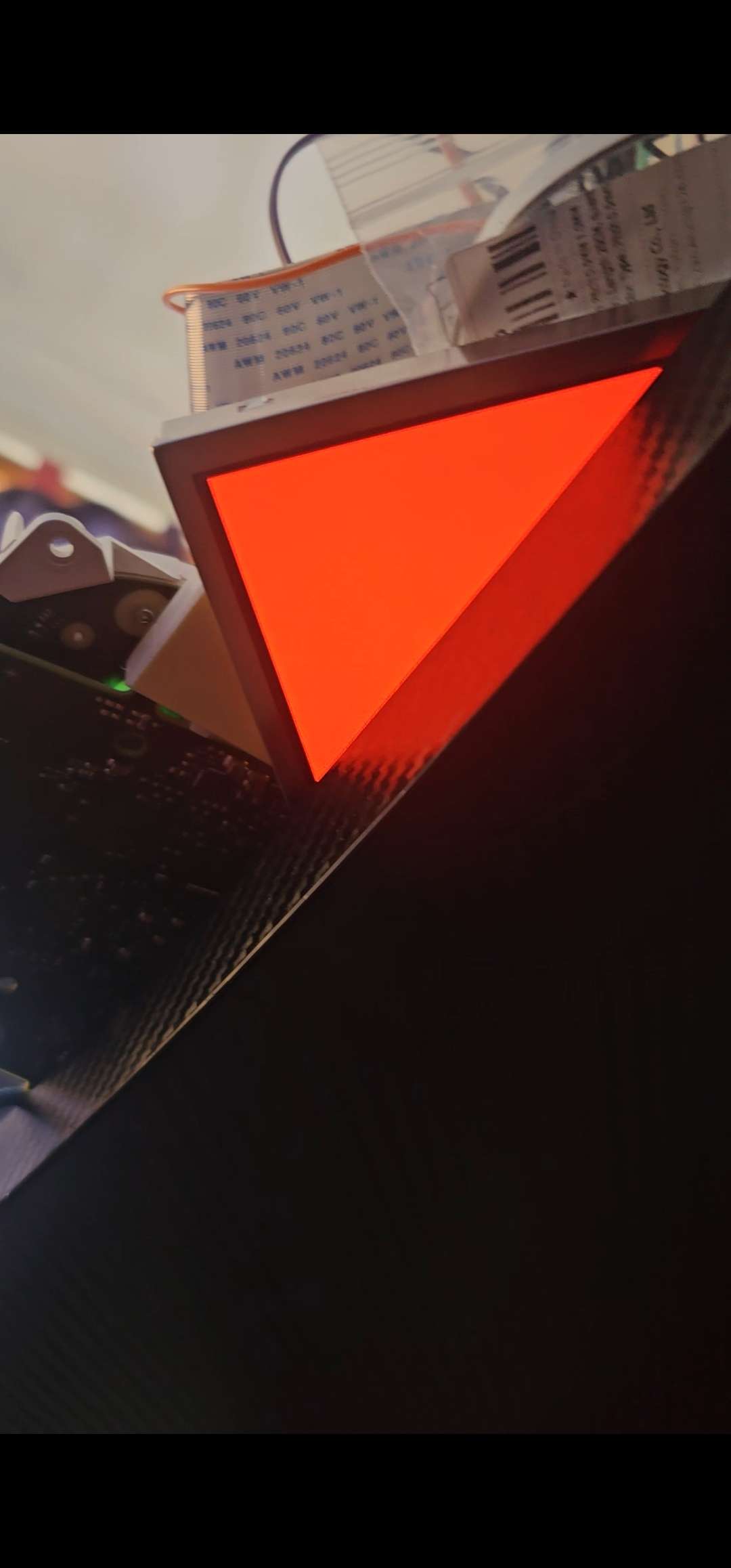
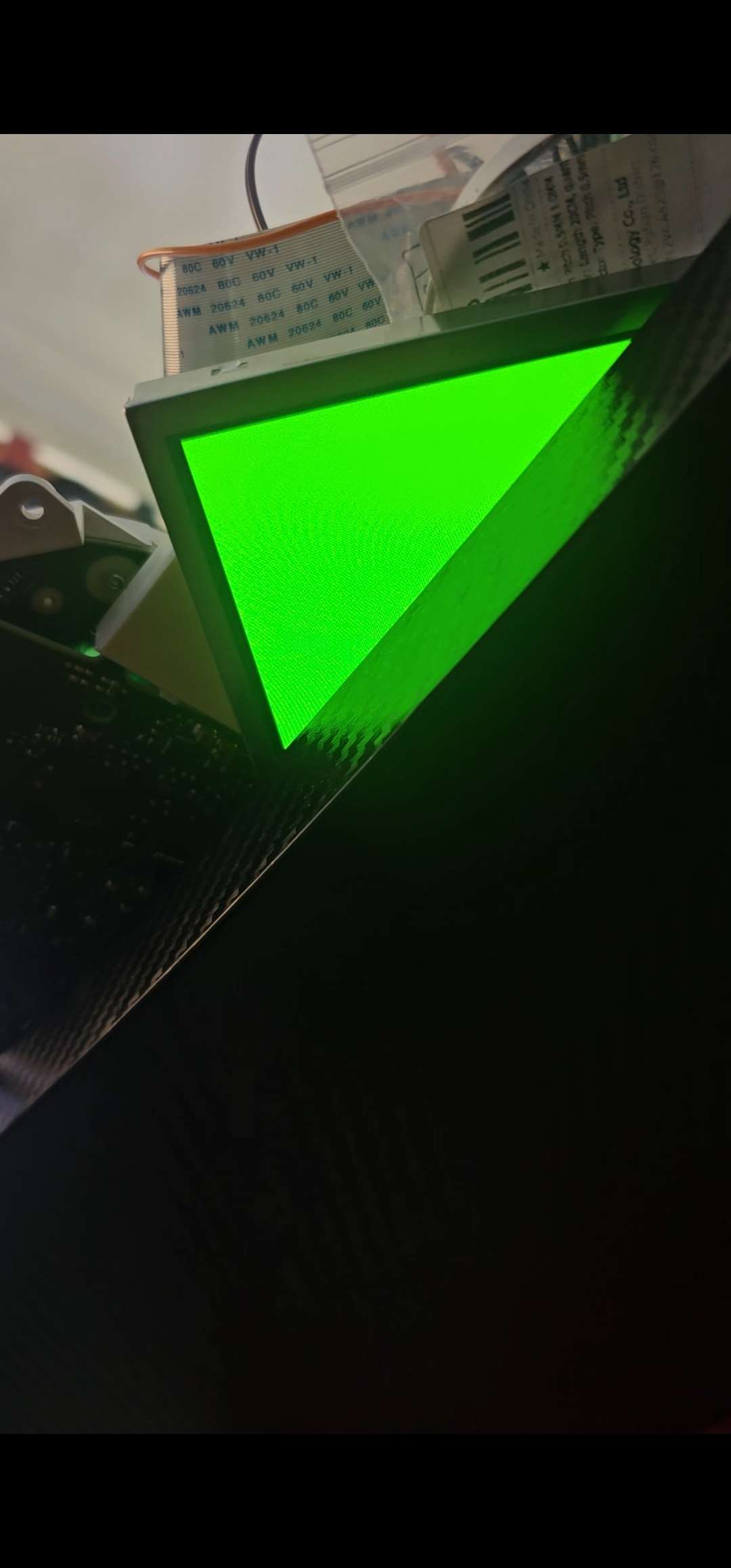
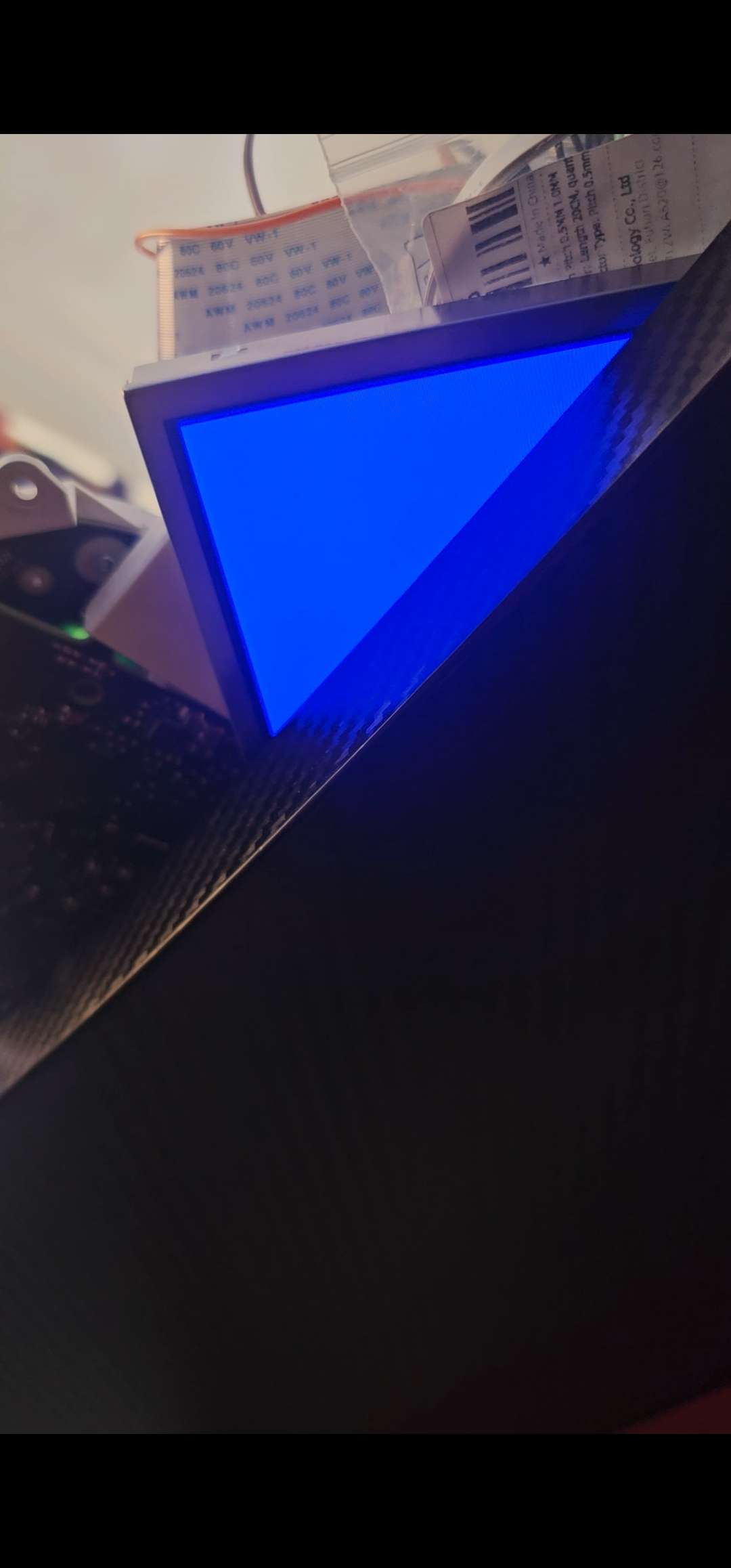
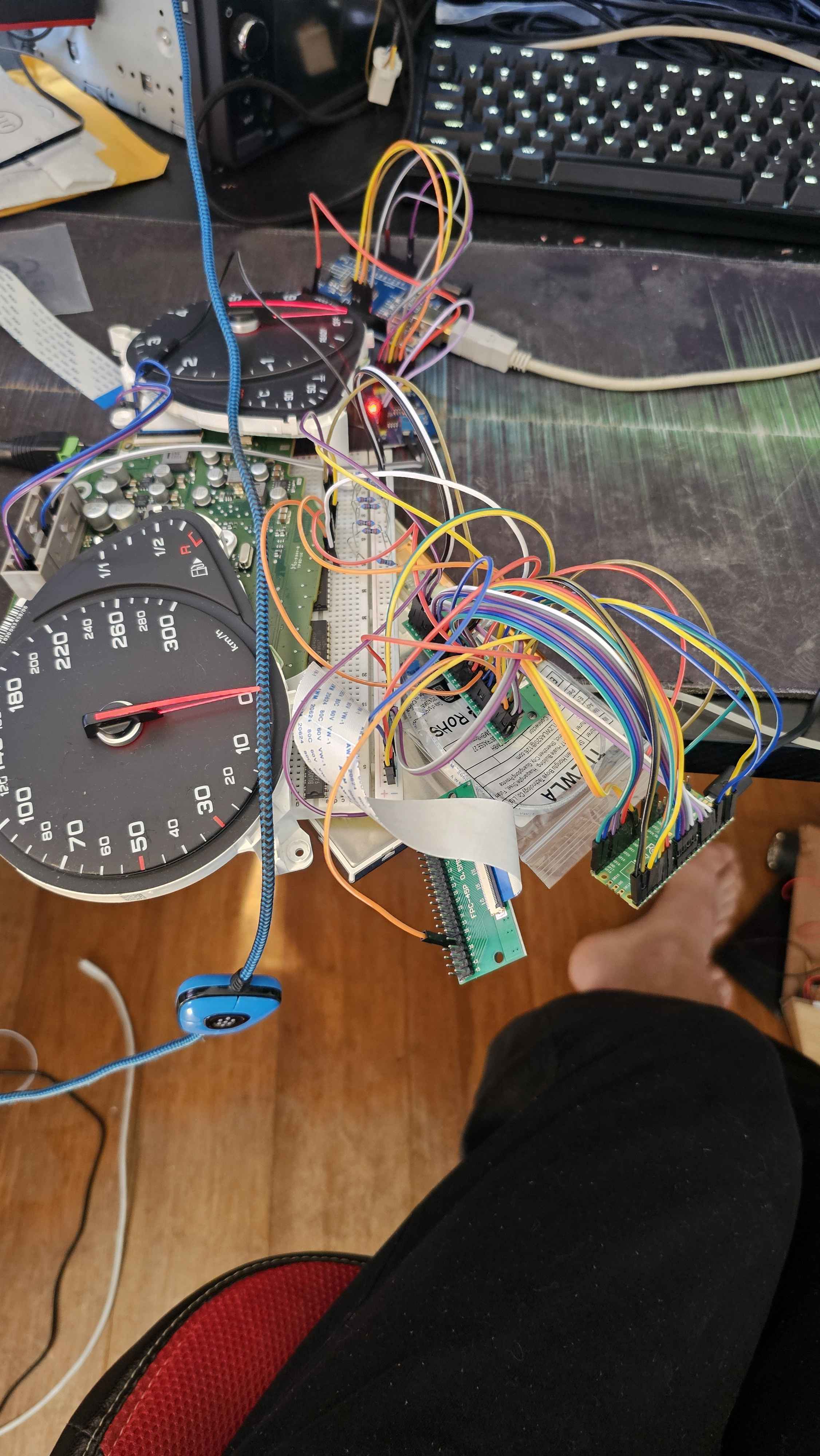
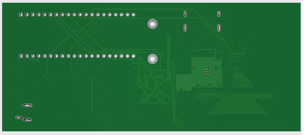
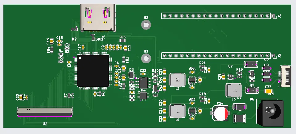
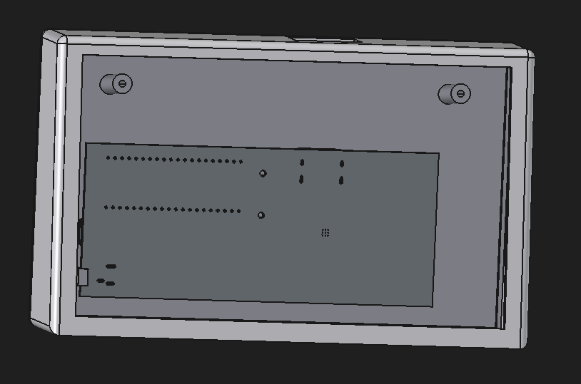
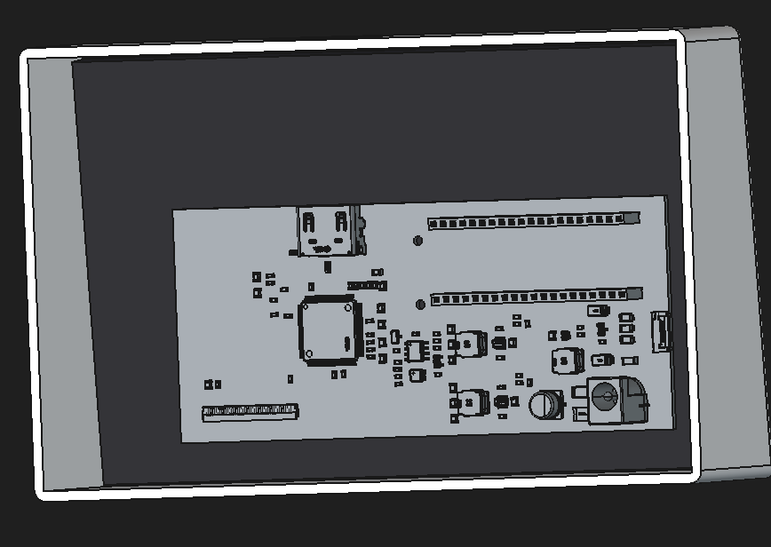
This screen comes from an Audi Q7 dashboard. Prior to this project, I was able to control the entire dashboard via CAN. After that, I wanted to control the LCD entirely independently, and use it as a standalone monitor. I have always found it interesting to reverse engineering things, so I believed this project would be a great start, and so far it has.
This is a standalone monitor, so it can display graphics or what not connected directly to your PC.
A HDMI cable will be plugged into the case, it will function as a secondary monitor, converting HDMI to Parallel RGB on the PCB, via a TFP401 microchip, and sending a SPI sequence from a Pico 2 to the panel.
Originally, I had tried to search for datasheets available for my panel, but couldn't find any. This meant I had to reverse engineer it myself entirely. I began by connecting the dashboard's ribbon to one FFC breakout board and the panel's flex to another, with jumper wires between them, so I could probe every pin for continuity and voltage with a multimeter while the panel was running. Many problems were met here, more in the journal.
Numbers are the breakout board labels.
| Label | Function | Notes |
|---|---|---|
| 1, 2, 13, 22, 31, 33, 37, 44, 45 | Ground | |
| 3 | Unknown | 1.5 kΩ pull-down to ground |
| 4, 38 | Power in | 3.3V |
| 5–12 | Blue B0–B7 | 5 = smallest bit |
| 14–21 | Green G0–G7 | 14 = smallest bit |
| 23–30 | Red R0–R7 | 23 = smallest bit |
| 32 | PCLK | Pixel clock |
| 34 | HSYNC | |
| 35 | VSYNC | |
| 36 | DE | Data enable |
| 39, 43 | Not connected | Unknown |
| 40 | SPI data (MOSI) | Setup commands |
| 41 | SPI chip select | Active low |
| 42 | SPI clock |
| Value | |
|---|---|
| Resolution | 800 × 480 |
| Pixel clock | ~26.8 MHz (cluster), 25 MHz (Pico) |
| Horizontal | HSYNC 10 px, back porch 6 px, active 800 px, front porch 106 px, total 922 px |
| Vertical | active 480 lines, front porch 8, VSYNC 4, back porch 8, total 500 lines |
| Refresh rate | ~58 Hz (cluster), ~54 Hz (Pico) |
| Sync polarity | HSYNC and VSYNC active low, DE active high |
The sequence that the cluster sends to the panel to 'stay alive', or a gamma/brightness setting. It consists of 3 wires at ~500 kHz. It starts ~25 ms after video starts, and without it the panel stays black.
| Step | Bytes (hex) | Delay after |
|---|---|---|
| 1 | 1B 50 00 | 2.15 ms |
| 2 | 1D 5C 00 | 2.15 ms |
| 3 | 10 00 | 2.15 ms |
| 4 | 08 80 | ~125.6 ms |
| 5 | 14 80 |
The cluster repeats the whole set every ~545.6 ms. What each register does is unknown.
The design is finished, including the PCB, case, and firmware, and is waiting on funding to order and build.
Breakout A = panel side, Breakout B = cluster side.
| Pico 2 | Breakout A | Signal |
|---|---|---|
| GP0 | 32 | PCLK |
| GP1 | 36 | DE |
| GP2 | 34 | HSYNC |
| GP27 | 35 | VSYNC |
| GP28 | — | Not connected (used internally by the Pico) |
| GP21 | 42 | SPI clock |
| GP22 | 40 | SPI data (MOSI) |
| GP26 | 41 | SPI chip select |
| GND | Ground rail | Ground |
| Colour | Bit | Breakout A | Pico 2 |
|---|---|---|---|
| Blue | B2 | 7 | GP5 |
| Blue | B3 | 8 | GP6 |
| Blue | B4 | 9 | GP7 |
| Blue | B5 | 10 | GP8 |
| Blue | B6 | 11 | GP3 |
| Blue | B7 | 12 | GP9 |
| Green | G2 | 16 | GP12 |
| Green | G3 | 17 | GP13 |
| Green | G4 | 18 | GP14 |
| Green | G5 | 19 | GP4 |
| Green | G6 | 20 | GP15 |
| Green | G7 | 21 | GP10 |
| Red | R2 | 25 | GP18 |
| Red | R3 | 26 | GP19 |
| Red | R4 | 27 | GP20 |
| Red | R5 | 28 | GP11 |
| Red | R6 | 29 | GP16 |
| Red | R7 | 30 | GP17 |
| Breakout A | Resistor | Why |
|---|---|---|
| 3 | 1 kΩ | 1.5 kΩ pull-down |
| 5, 6 | 2.2 kΩ each | Blue B0–B1 held low (unused) |
| 14, 15 | 2.2 kΩ each | Green G0–G1 held low (unused) |
| 23, 24 | 2.2 kΩ each | Red R0–R1 held low (unused) |
| Connection | Purpose |
|---|---|
| B4 → A4 | Panel power from the cluster |
| B38 → A38 | Panel power from the cluster |
| A1, 2, 13, 22, 31, 33, 37, 44, 45 → ground rail | Panel grounds |
| B1, 22, 44 → ground rail | Cluster ground |
| A39, A43 | Left unconnected |
| 10-pin backlight ribbon | Stays plugged into the cluster |
Power order: cluster on first, then plug in the Pico.
The TFP401 converts HDMI to parallel RGB, and the SPI sequence comes from the Pico
HDMI input, into the TFP401 chip, outputting TTL/Parallel RGB, and connects to the 45-pin connector
12V input, converted to 5V, 3.3V, and 22.5V, via buck converters and boost converters, with a resettable fuse (F2)
Driven by the 22.5V, with 3 LED strings that return through a 20mA constant-current chip. A MOSFET then switches them with PWM from the Pico for brightness.
SPI sequence on pins 4-6 of the 45-pin connector, the backlight, and the EDID.
A memory chip (AT24C02 EEPROM) on the HDMI's DDC lines. The Pico writes it through a level shifter, and it tells the PC the screens resolution, and monitor name.
Currently, the Pico code is MicroPython, written and run through Thonny. It generates the timing signals (PCLK, HSYNC, VSYNC, DE) using the Pico's PIO hardware, sends the SPI sequence, and controls the red, green and blue bits. The test firmware was written with help from Claude (AI), and is able to send the SPI sequence, turn backlight on, and write the EDID with the correct resolution and monitor name. Code can be found here, the file is cluster2hdmi_main.py. It is still, however, untested, as the PCB hasn't been ordered yet.
All prices in USD (AliExpress prices converted from AUD). Full list with notes: bom.csv. Every part on the PCB (with LCSC numbers) is in KiCad/Fabrication/Cluster2HDMI_BOM_JLC_v2.csv.
| Item | Qty | Cost (USD) | Where |
|---|---|---|---|
| Cluster2HDMI PCB (4-layer, 1.6 mm, HASL) | 5 | 29.40 | JLCPCB |
| PCB assembly (Economic PCBA) | 2 | 97.14 | JLCPCB |
| JLCPCB shipping | 1 | 12.07 | JLCPCB |
| JLCPCB discount | 1 | -10.00 | JLCPCB |
| JLCPCB payment fee (PayPal) | 1 | 0.64 | JLCPCB |
| 12 V 2 A power adapter (AU plug, 5.5 x 2.1 mm) | 1 | 2.81 | AliExpress |
| 1x20 2.54 mm female pin socket (pack of 10) | 1 pack | 1.13 | AliExpress |
| Pin socket shipping | 1 | 1.65 | AliExpress |
| M2 x 30 mm pan head screw (pack of 25) | 1 pack | 2.06 | AliExpress |
| M2 x 8 mm pan head screw (pack of 25) | 1 pack | 1.47 | AliExpress |
| HDMI cable 2 m | 1 | 3.76 | AliExpress |
| Raspberry Pi Pico 2 | 1 | owned | Raspberry Pi |
| Audi Q7 4M0 920 781 A cluster (LCD panel) | 1 | owned | eBay |
| PETG filament (~100 g for the case) | 1 | owned | - |
| Total | 142.13 |
MIT, see LICENSE.
| Qty | Value | Footprint | References |
|---|---|---|---|
| 15 | 10n | Capacitor_SMD:C_0603_1608Metric | C2, C3, C4, C6, C7, C8, C9, C10, C12, C13, C14, C15, C17, C18, C19 |
| 10 | 10K | Resistor_SMD:R_0603_1608Metric | R1, R2, R3, R4, R5, R7, R8, R15, R16, R23 |
| 10 | 22u | Capacitor_SMD:C_0805_2012Metric | C1, C5, C11, C16, C30, C31, C32, C39, C40, C41 |
| 6 | 100n | Capacitor_SMD:C_0603_1608Metric | C21, C22, C26, C27, C36, C37 |
| 4 | 10u | Capacitor_SMD:C_0805_2012Metric | C20, C25, C29, C35 |
| 4 | GZ2012D601TF | Inductor_SMD:L_0805_2012Metric | FB1, FB2, FB3, FB4 |
| 3 | NSI45020T1G | easyeda2kicad:SOD-123F_L2.8-W1.8-LS3.7-RD | U8, U9, U10 |
| 3 | SWPA6045S100MT | easyeda2kicad:IND-SMD_L6.0-W6.0_SWPA6045S | L1, L2, L3 |
| 2 | 100K | Resistor_SMD:R_0603_1608Metric | R17, R22 |
| 2 | 1K | Resistor_SMD:R_0603_1608Metric | R9, R20 |
| 2 | 4.7K | Resistor_SMD:R_0603_1608Metric | R13, R14 |
| 2 | 47K | Resistor_SMD:R_0603_1608Metric | R10, R11 |
| 2 | AO3400A | easyeda2kicad:SOT-23-3_L2.9-W1.3-P1.90-LS2.4-BR | Q1, Q2 |
| 2 | Conn_01x20_Socket | Connector_PinSocket_2.54mm:PinSocket_1x20_P2.54mm_Vertical | J1, J2 |
| 2 | MountingHole_2.2mm_M2_Pad | MountingHole:MountingHole_2.2mm_M2_Pad | H1, H2 |
| 2 | SS16_C84578 | easyeda2kicad:SMA_L4.4-W2.6-LS5.0-RD | D4, D6 |
| 2 | TPD4E05U06DQAR_C138714 | easyeda2kicad:USON-10_L2.5-W1.0-P0.50-BL | D1, D2 |
| 2 | TPS54202DDCR | easyeda2kicad:SOT-23-6_L2.9-W1.6-P0.95-LS2.8-BL | U5, U6 |
| 1 | 100p | Capacitor_SMD:C_0603_1608Metric | C23 |
| 1 | 120K | Resistor_SMD:R_0603_1608Metric | R19 |
| 1 | 13K | Resistor_SMD:R_0603_1608Metric | R18 |
| 1 | 200K | Resistor_SMD:R_0603_1608Metric | R12 |
| 1 | 22K | Resistor_SMD:R_0603_1608Metric | R21 |
| 1 | 33 | Resistor_SMD:R_0603_1608Metric | R6 |
| 1 | 4.7u | Capacitor_SMD:C_1206_3216Metric | C33 |
| 1 | 47u | Capacitor_SMD:CP_Elec_6.3x5.4 | C24 |
| 1 | 56p | Capacitor_SMD:C_0603_1608Metric | C38 |
| 1 | 75p | Capacitor_SMD:C_0603_1608Metric | C28 |
| 1 | AT24C02C-SSHM-T | easyeda2kicad:SOIC-8_L5.0-W4.0-P1.27-LS6.0-BL | U3 |
| 1 | BAT54C | Package_TO_SOT_SMD:SOT-23 | D3 |
| 1 | FH34SRJ-45S-0.5SH | easyeda2kicad:FPC-SMD_45P-P0.50_FH34SRJ-45S-0.5SH-50 | U2 |
| 1 | FPC-05F-10PH20 | easyeda2kicad:FPC-SMD_10P-P0.50_XUNPU_FPC-05F-10PH20 | FPC1 |
| 1 | HDMI-019S | easyeda2kicad:HDMI-SMD_HDMI-019S | HDMI1 |
| 1 | PCA9306 | Package_SO:SSOP-8_2.95x2.8mm_P0.65mm | U4 |
| 1 | PJ-044A | easyeda2kicad:DC-IN-TH_PJ-044A | DC1 |
| 1 | SS34_C8678 | easyeda2kicad:SMA_L4.3-W2.6-LS5.2-RD | D7 |
| 1 | TFP401APZPR | easyeda2kicad:HTQFP-100_L14.0-W14.0-P0.50-LS16.0-BL-EP6.2 | U1 |
| 1 | TPS61169DCKR | easyeda2kicad:SC-70-5_L2.1-W1.3-P0.65-LS2.1-BR | U7 |
| 1 | mSMD110-16V | easyeda2kicad:F1812 | F2 |
It measures 128 × 55 mm and has 4 copper layers, 1.61 mm thick.
96 parts, built around the TPS54202DDCR, TFP401APZPR, AT24C02C-SSHM-T and FH34SRJ-45S-0.5SH(50). The full list of its parts is on this page, with links to each part's symbol and footprint where PCBKit's library has them.
From the vkar9898/Cluster2HDMI repository on GitHub, at the commit this page was made from: the board is KiCad/Cluster2HDMI/Cluster2HDMI.kicad_pcb and its schematic KiCad/Cluster2HDMI/Cluster2HDMI.kicad_sch. PCBKit opens the board in the browser, with nothing to install.
Its repository publishes it under the MIT licence: you may reuse it on that licence's terms (keep the author's notice, and for a copyleft licence share your changes alike).
Maillouski/Model-2-IO-Board-for-m2m3
Drop-in replacement for the Sega 837-10539 I/O board (Daytona USA twin, Model 2), built around an Arduino Mega 2560. KiCad 10, CC BY-NC-SA 4.0.

PaulBichl/vibepcb-smu
VibePCB example: 4-quadrant SMU (+-30 V / +-1 A, USB-C PD, Ethernet) designed with an LLM


openconcepts-ar/accel2d
This project aims to provide a graphics server system based on hardware accelerated graphics, and a easy way to develop the graphics primitives.

PicoballoonLabs/Debug-Boards
Hardware designs for the integrated debug probe, debug adapter, flex debug cables and RF VNA calibrator

mymakercorner/Leyden_Jar
A modernized controller PCB for the Brand New Model F and Beam Spring keyboards


Scottapotamas/spe-marine-node
Prototype project to build an underwater sensor node, powered by and communicating with the surface via Single Pair Ethernet (10BASE-T1L + 802.3cg)