
2 layers100 × 113 mm

 VirToReal/VirToCut
Building and controlling a Plate Saw Machine
Modified2 is an open-source printed circuit board by VirToReal, from the VirToReal/VirToCut repository on GitHub, published under the GPL-3.0 licence. It is a 2-layer board of 100 × 112 mm with 61 parts on 78 nets, routed with 746 tracks and 10 vias.
It is built around the ULN2803. Its parts include 34 resistors, 18 connectors, 3 fuses, 2 ICs and 2 switches.
I moved my repositories to gitlab, please do any suggestions there: https://gitlab.com/Hirmer/VirToCut
Thank you!

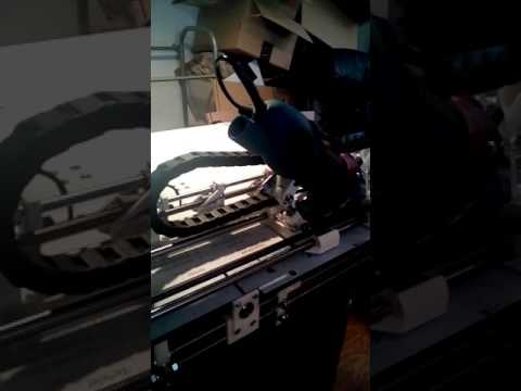
This is a Plate Saw Machine, which cuts straight stripes from a plate. The machine can be controlled via Software automatically, or trough the software/control-panel manually. The cutting-distance of the saw blade and the material feed, too. The thickness of the saw blade will be added automatically in manual-mode.
To control the saw via software in automatic-mode, you can use a code syntax i developed for this machine which will look like that:
A50 B300 // Feed Material 50mm and cut into that material 300mm.
A50 B300
A30 B300
A30 B300
A10 B300
ROTATE // Saw stops, user have to rotate the plate 90°, some visual assistance shows user which stripes have to be placed into the machine (not ready yet) and confirms via software/hardware- button.
A100 B100
A100 B100
WAIT // Saw stops, user have to place a new pair of stripes into the machine and confirms to proceed.
A80 B60
A80 B60
WAIT // Saw stops, user have to place a new pair of stripes into the machine and confirms to proceed.
A50 B20
A50 B20
A50 B20
The result will look like this:

This is a project about building and controlling a Plate Saw Machine. You can generate your own components by using the "ConstructionTemplate.scad"-File with OpenSCAD (http://www.openscad.org). Every component are adjustable in their dimensions as described in the “OpenScadDokumentation”-Folder. In OpenSCAD you also able to switch between the complete overview as the picture below and each single printable part as listened in the “OpenScadDokumentation”-Folder by using the “printmode”-Variable within the “ConstructionTemplate.scad”-File. All details are described in the file itself.

To get this project to work, you need some experience in printing parts with a 3D-Printer. Also some knowledge in electrical engineering are required, because you have to make a PCB and wire up a power-supply, raspberry-pi and an arduino-mega-2560 + ramps-shield. My files for milling/etching the PCB are to be found in the "KiCad"-Folder. The Files can be edited with the KiCad-Software (http://kicad.org). I used FlatCam (http://flatcam.org) to mill the "Gerber"-Files from KiCad.
I use Python to send G-Code-Commands from the Raspberry-Pi to the Arduino over a serial interface. Marlin (http://marlinfw.org) is running on the Arduino and interprets the received G-Code-Commands and drives the engines with the RAMPS1.4 Shield (http://reprap.org/wiki/RAMPS_1.4). My Marlin-Configuration can be found in the "Marlin Firmware"-Folder.
The Python-Software can be found in the "Python Software"-Folder. At the moment its only available in German. If its necessary, I will rewrite it in english, too. The Software is already able to generate saw-pattern-templates, to cut a plate in different sized plates automatically.


But consider, the project is not fully completed yet. Some smaller improvements still has to be made:
Structure on the material feeder, which prevents the material from rotating. Thought on something like a feather tensioned clamp.
Some smaller software updates (don't find the time at the moment).
Any help would be appreciated.
Contact me if you want futher informations!
| Qty | Value | Footprint | References |
|---|---|---|---|
| 22 | R10k | Resistors_ThroughHole:Resistor_Horizontal_RM10mm | R1, R3, R10, R11, R12, R13, R16, R17, R22, R23, R24, R25, R32, R33, R34, R35 +6 |
| 8 | R240 | Resistors_ThroughHole:Resistor_Horizontal_RM10mm | R18, R19, R20, R21, R26, R27, R28, R29 |
| 3 | 1A | Fuse_Holders_and_Fuses:Fuseholder5x20_horiz_SemiClosed_Casing10x25mm | F1, F2, F3 |
| 2 | CONN_01X02 | Pin_Headers:Pin_Header_Straight_1x02 | P16, P17 |
| 2 | CONN_T_Res | Pin_Headers:Pin_Header_Straight_1x04 | P13, P14 |
| 2 | R470 | Resistors_ThroughHole:Resistor_Horizontal_RM10mm | R14, R15 |
| 2 | ULN2803 | Housings_DIP:DIP-18_W7.62mm | U1, U2 |
| 1 | CONN_01X02 | Terminal_Blocks:TerminalBlock_Pheonix_MPT-2.54mm_2pol | P15 |
| 1 | CONN_01X05 | Terminal_Blocks:TerminalBlock_Pheonix_PT-3.5mm_6pol | P10 |
| 1 | CONN_01X06 | Terminal_Blocks:TerminalBlock_Pheonix_PT-3.5mm_6pol | P10.1 |
| 1 | CONN_Aux_Res | Pin_Headers:Pin_Header_Straight_1x07 | P5 |
| 1 | CONN_RS232 | Pin_Headers:Pin_Header_Straight_1x02 | P2 |
| 1 | CONN_Reset | Pin_Headers:Pin_Header_Straight_1x02 | P3 |
| 1 | CONN_SUPPLY | Pin_Headers:Pin_Header_Straight_1x02 | P4 |
| 1 | CONN_SUPPLY2 | Pin_Headers:Pin_Header_Straight_1x08 | P1 |
| 1 | CONN_TS_Snt | Pin_Headers:Pin_Header_Straight_1x04 | P12 |
| 1 | CONN_TS_Vr | Pin_Headers:Pin_Header_Straight_1x04 | P9 |
| 1 | CONN_TS_Zk | Pin_Headers:Pin_Header_Straight_1x04 | P11 |
| 1 | CONN_TV_GZk | Pin_Headers:Pin_Header_Straight_1x04 | P8 |
| 1 | CONN_TV_Vr | Pin_Headers:Pin_Header_Straight_1x04 | P6 |
| 1 | CONN_TV_Zk | Pin_Headers:Pin_Header_Straight_1x04 | P7 |
| 1 | R12k | Resistors_ThroughHole:Resistor_Horizontal_RM10mm | R31 |
| 1 | R6k2 | Resistors_ThroughHole:Resistor_Horizontal_RM10mm | R30 |
| 1 | RASPBERRY_IO | Pin_Headers:Pin_Header_Straight_2x13 | RPi1_P1 |
| 1 | RELAY_Hakrsae | EigenbauFootprints:Relais_FIN94_Print-Socket | K2 |
| 1 | RELAY_Stbsgr | EigenbauFootprints:Relais_FIN94_Print-Socket | K1 |
| 1 | RPi2_P5 | Pin_Headers:Pin_Header_Straight_2x04 | CONN_02X4 |
It measures 100 × 112 mm and has 2 copper layers, 1.6 mm thick.
61 parts, built around the ULN2803. The full list of its parts is on this page, with links to each part's symbol and footprint where PCBKit's library has them.
From the VirToReal/VirToCut repository on GitHub, at the commit this page was made from: the board is KiCad/modified2.kicad_pcb. PCBKit opens the board in the browser, with nothing to install.
Its repository publishes it under the GPL-3.0 licence: you may reuse it on that licence's terms (keep the author's notice, and for a copyleft licence share your changes alike).


Believotron/Believotronics
Believotronics is a low-cost DIY open source robotics platform you can print and build at work or from home. Our first projects are a MicroscopeBot and a ThroughholeSolderBot.


klaus-liebler/sensact
Es gibt vier Namespaces für Nachrichten "REQUEST" und "RESPONSE", "EVENT" und "ACKNOWLEDGE". Dies wird mit den beiden LSB des Versions-Namespace-Bytes erklärt (Somit bleiben 64 Versionierungsmöglichkeiten) Alle vier…


accelerando-consulting/star-of-devops
The Star of Devops - an LED christmas star that you can control and update over wifi
