

2 layers31.7 × 58.4 mm
 ashishjoy19/Mini-Plotter
The PCB Files for the Mini-Plotter
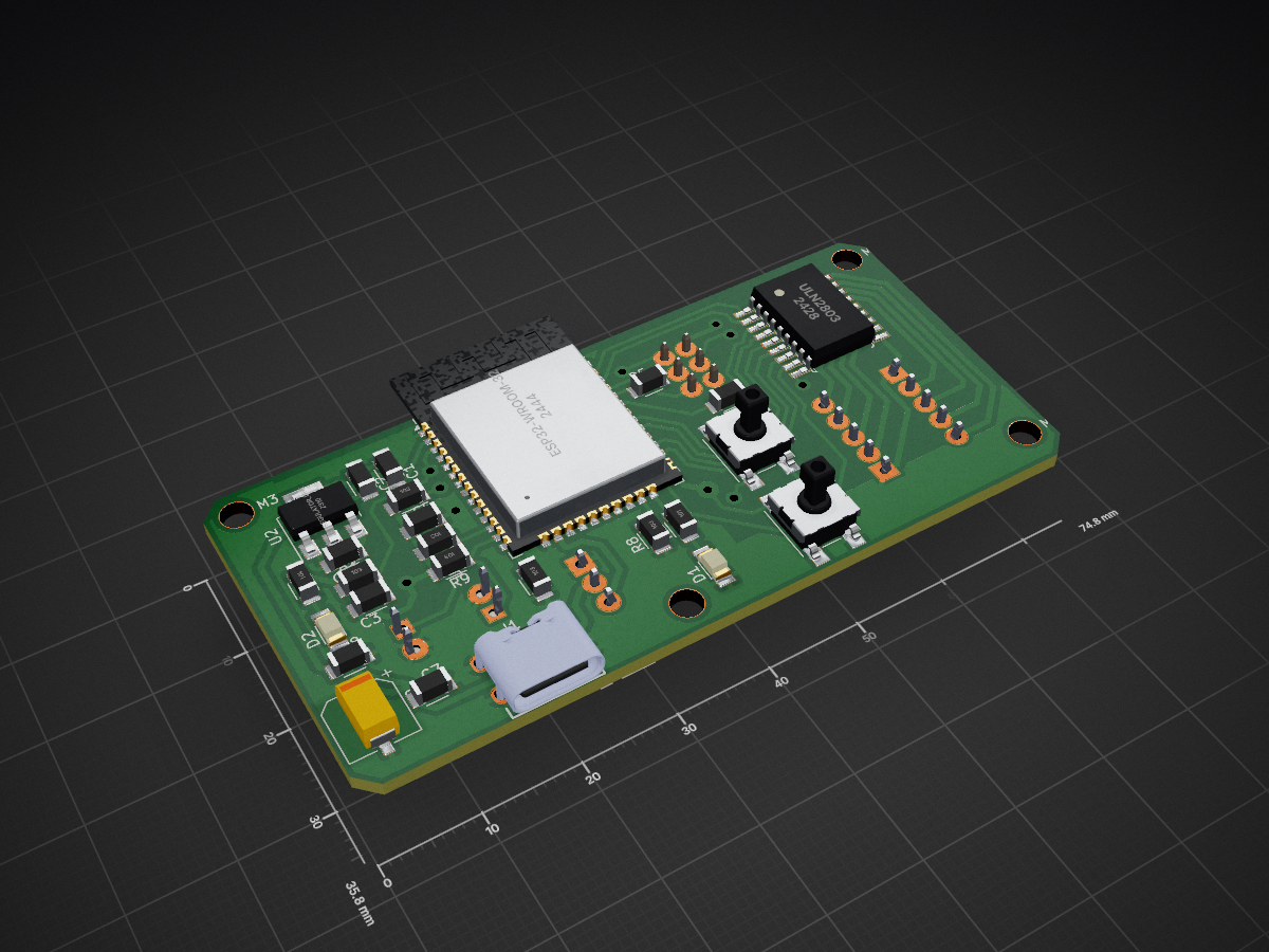
Pen Plotter is an open-source printed circuit board by ashishjoy19, from the ashishjoy19/Mini-Plotter repository on GitHub. It is a 2-layer board of 74.8 × 35.8 mm with 36 parts on 49 nets, routed with 402 tracks and 11 vias.
It is built around the ESP32-WROOM-32E and ULN2803. Its parts include 10 resistors, 8 capacitors, 7 connectors, 3 ICs and 2 diodes. It belongs with the ESP32 boards of this library.
This document covers the electronics subsystem of the Mini Plotter V project.
It is intended as a reference for coworkers, fabrication, debugging, and replication of the electronics and PCB.
Board Details
| Parameter | Value |
|---|---|
| PCB Name | Mini Plotter V2 – Electronics |
| Layers | 2 |
| Thickness | 1.6 mm |
| Copper Weight | 1 oz |
| Assembly | Through-hole + SMD |
| Logic Voltage | 3.3V |
| Motor Voltage | 5V DC |
⚠️ Important
| Label | GPIO |
|---|---|
| IN1 | GPIO 23 |
| IN2 | GPIO 22 |
| IN3 | GPIO 21 |
| IN4 | GPIO 19 |
| Label | GPIO |
|---|---|
| IN5 | GPIO 18 |
| IN6 | GPIO 17 |
| IN7 | GPIO 16 |
| IN8 | GPIO 4 |
| Label | GPIO |
|---|---|
| SIGNAL | GPIO 13 |
| VCC | 5V |
| GND | GND |
| Switch | Signal GPIO | Ground |
|---|---|---|
| X Limit | GPIO 27 | GND |
| Y Limit | GPIO 14 | GND |
This document provides electronics design guidelines for using the ESP32-WROOM-32E module in custom PCBs.
It focuses on:
⚠️ All GPIOs are 3.3V only. Do NOT apply 5V.
::contentReference[oaicite:0]{index=0}
| Pin | Requirement |
|---|---|
| 3V3 | Stable 3.3V supply (≥ 600 mA peak) |
| GND | Solid ground connection |
| EN | Pulled HIGH (via 10kΩ) |
| IO0 | Pulled HIGH (via 10kΩ) |
| TX0 (GPIO1) | UART TX for flashing |
| RX0 (GPIO3) | UART RX for flashing |
| IO0 State | Boot Mode |
|---|---|
| HIGH | Normal boot (flash) |
| LOW | UART download (flashing) |
To flash firmware:
These pins are sampled at reset.
Incorrect levels will prevent booting.
| GPIO | Default State | Function |
|---|---|---|
| GPIO0 | Pull-up | Boot mode select |
| GPIO2 | Pull-down | Must be LOW at boot |
| GPIO4 | Pull-down | Boot config |
| GPIO5 | Pull-up | Boot config |
| GPIO12 | Pull-down | Flash voltage select |
| GPIO15 | Pull-up | Boot config |
⚠️ Do not drive these pins externally at boot unless you know the impact.
| GPIO | Reason |
|---|---|
| GPIO6–11 | Connected to internal flash (DO NOT USE) |
| GPIO0 | Boot mode pin |
| GPIO2 | Must be LOW during boot |
| GPIO12 | Affects flash voltage |
| GPIO15 | Boot strapping pin |
| GPIO | Notes |
|---|---|
| GPIO4 | Safe after boot |
| GPIO5 | Safe after boot |
| GPIO16–19 | General purpose |
| GPIO21–23 | I²C / SPI friendly |
| GPIO25–27 | ADC capable |
| GPIO32–33 | ADC + low power |
| GPIO34–39 | Input-only (ADC) |
| Pin | Recommended |
|---|---|
| EN | 10kΩ pull-up to 3.3V |
| IO0 | 10kΩ pull-up |
| GPIO2 | 10kΩ pull-down |
| GPIO12 | 10kΩ pull-down |
| GPIO15 | 10kΩ pull-up |
⚠️ Internal pulls exist but external resistors improve reliability.
For USB-UART auto programming:
| ESP32 Pin | USB-UART Signal |
|---|---|
| EN | DTR (via transistor) |
| IO0 | RTS (via transistor) |
| RX0 | TXD |
| TX0 | RXD |
This allows flashing via:
⚠️ Brownouts are the #1 cause of ESP32 instability.
⚠️ Very Important
❌ Powering ESP32 from 5V
❌ Using GPIO6–11
❌ Driving strapping pins at boot
❌ Weak 3.3V regulator
❌ Traces under antenna
This document is intended for PCB designers and electronics engineers working with ESP32-WROOM-32E in custom hardware.
Keep this file updated if pin usage or constraints change.
| Qty | Value | Footprint | References |
|---|---|---|---|
| 6 | 10K | fab:R_1206 | R1, R4, R8, R9, R10, R11 |
| 4 | ~ | fab:MountingHole_M3 | H1, H2, H3, H4 |
| 3 | 0.1uF | fab:C_1206 | C2, C7, C8 |
| 3 | 10uF | fab:C_1206 | C1, C4, C5 |
| 2 | 0 | fab:R_1206 | R5, R6 |
| 2 | 100 | fab:R_1206 | R2, R3 |
| 1 | 1uF | fab:C_1206 | C3 |
| 1 | 6120XX21621_61200621621 | 6 Pin Male-Box Header:61200621621 | J5 |
| 1 | Boot-GPIO0 | fab:Button_Omron_B3SN_6.0x6.0mm | SW2 |
| 1 | CP_Elec_100uF_Panasonic_EEE-FN1E101UL | fab:CP_Elec_100uF_Panasonic_EEE-FN1E101UL | C9 |
| 1 | ESP32-WROOM-32E | RF_Module:ESP32-WROOM-32D | U1 |
| 1 | Green | fab:LED_1206 | D2 |
| 1 | Motor 1 | B5B-XH-A:JST_B5B-XH-A | J2 |
| 1 | Motor 2 | B5B-XH-A:JST_B5B-XH-A | J3 |
| 1 | Red | fab:LED_1206 | D1 |
| 1 | Regulator_Linear_3.3V_1A_DiodesIncorporated | fab:SOT-223-3_TabPin2 | U2 |
| 1 | Reset-EN | fab:Button_Omron_B3SN_6.0x6.0mm | SW1 |
| 1 | Servo | B3B-XH-A:JST_B3B-XH-A | J4 |
| 1 | ULN2803 | ULN2803:SO18L | U4 |
| 1 | USB4125-GF-A_REVA2 | USB4125-GF-A_REVA2:GCT_USB4125-GF-A_REVA2 | J1 |
| 1 | X Lim | B2B-XH-A_LF__SN_:JST_B2B-XH-A_LF__SN_ | J8 |
| 1 | Y Lim | B2B-XH-A_LF__SN_:JST_B2B-XH-A_LF__SN_ | J6 |
It measures 74.8 × 35.8 mm and has 2 copper layers, 1.6 mm thick.
36 parts, built around the ESP32-WROOM-32E and ULN2803. The full list of its parts is on this page, with links to each part's symbol and footprint where PCBKit's library has them.
From the ashishjoy19/Mini-Plotter repository on GitHub, at the commit this page was made from: the board is Pen_Plotter/Pen_Plotter.kicad_pcb and its schematic Pen_Plotter/Pen_Plotter.kicad_sch. PCBKit opens the board in the browser, with nothing to install.
Its repository states no licence, so its author keeps all rights: ask ashishjoy19 before reusing the design.

Believotron/Believotronics
Believotronics is a low-cost DIY open source robotics platform you can print and build at work or from home. Our first projects are a MicroscopeBot and a ThroughholeSolderBot.


klaus-liebler/sensact
Es gibt vier Namespaces für Nachrichten "REQUEST" und "RESPONSE", "EVENT" und "ACKNOWLEDGE". Dies wird mit den beiden LSB des Versions-Namespace-Bytes erklärt (Somit bleiben 64 Versionierungsmöglichkeiten) Alle vier…


accelerando-consulting/star-of-devops
The Star of Devops - an LED christmas star that you can control and update over wifi
