2 layers74.5 × 49 mm
EEG
wangq22/ADS1299-BioAmp
ADS1299 BioAmp is an 8-channel biopotential acquisition board designed for research and development of EEG, EMG, ECG, and other low-amplitude bioelectrical signals.
76 parts2
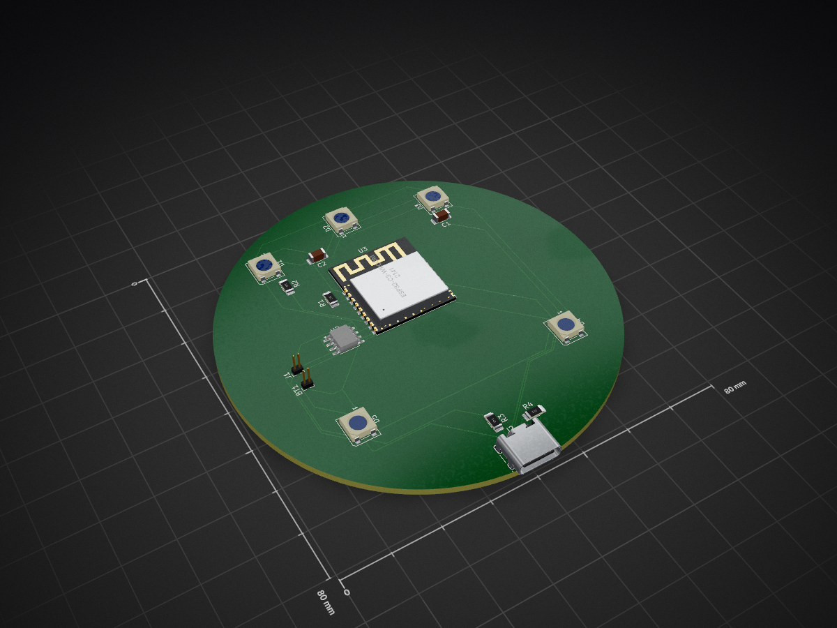
 vindognz/QuackOverflow
A wirelessly-charged LED rubber duck for debugging. Custom PCB with RGB LEDs and rechargeable battery fits inside a Kmart duck. Charges on a 3D-printed "DEBUGGING IN PROGRESS" stand.
Duck pcb is an open-source printed circuit board by vindognz, from the vindognz/QuackOverflow repository on GitHub. It is a 2-layer board with 16 parts on 32 nets, routed with 151 tracks and 0 vias.
It is built around the ESP32-C3-WROOM-02-H4, TP4056-42-ESOP8 and WS2812B. Its parts include 5 diodes, 4 resistors, 2 capacitors, 2 ICs and 2 connectors. It belongs with the ESP32 and RISC-V boards of this library.


A wirelessly-charged LED rubber duck for debugging. Custom PCB with RGB LEDs and rechargeable battery fits inside a Kmart duck. Charges on a 3D-printed "DEBUGGING IN PROGRESS" stand. Because explaining your code to a glowing duck is more fun than regular rubber duck debugging.
Rubber duck debugging is a real technique where programmers explain their code line-by-line to an inanimate object (traditionally a rubber duck) to help spot bugs. I was gifted this duck as a coding companion for my birthday. I always imagined it glowing for those 2am debugging sessions. This project aims to make that dream a reality.
| Qty | Value | Footprint | References |
|---|---|---|---|
| 5 | WS2812B | LED_SMD:LED_WS2812B_PLCC4_5.0x5.0mm_P3.2mm | D1, D2, D3, D4, D5 |
| 2 | 100nF | Capacitor_SMD:C_1206_3216Metric_Pad1.33x1.80mm_HandSolder | C1, C2 |
| 2 | 5.1k | Resistor_SMD:R_1206_3216Metric_Pad1.30x1.75mm_HandSolder | R3, R4 |
| 1 | 10kΩ | Resistor_SMD:R_1206_3216Metric_Pad1.30x1.75mm_HandSolder | R1 |
| 1 | 330Ω | Resistor_SMD:R_1206_3216Metric_Pad1.30x1.75mm_HandSolder | R2 |
| 1 | Battery_Cell | Connector_PinHeader_1.00mm:PinHeader_1x02_P1.00mm_Vertical | BT1 |
| 1 | ESP32-C3-WROOM-02 | Espressif:ESP32-C3-WROOM-02 | U3 |
| 1 | Qi_Reciever | Connector_PinHeader_1.00mm:PinHeader_1x02_P1.00mm_Vertical | J1 |
| 1 | TP4056-42-ESOP8 | Package_SO:SOIC-8-1EP_3.9x4.9mm_P1.27mm_EP2.41x3.3mm_ThermalVias | U2 |
| 1 | USB_C_Receptacle_USB2.0_14P | Connector_USB:USB_C_Receptacle_HRO_TYPE-C-31-M-12 | J2 |
wangq22/ADS1299-BioAmp
ADS1299 BioAmp is an 8-channel biopotential acquisition board designed for research and development of EEG, EMG, ECG, and other low-amplitude bioelectrical signals.


Skaut0071/SlimeVR_Tracker
Cutsom PCB based on SlimeVR project for Full Body Tracking for Virtual Reality without need of expensive base stations.

abnegative2904/The-smart-City-Sentinel---A-Modular-PCB-for-intelligent-environment-monitoring
This setup provides a comprehensive solution for monitoring environmental conditions, making it ideal for applications like smart agriculture, home automation, and environmental research.

darshg321/Minicopter
Compact and precise ESP-32 based drone capable of autonomous pathing, built from scratch


kothanikhil9/Environmental-Monitoring-Node
The system continuously measures environmental temperature using a digital sensor and processes the data through a microcontroller.

SailingTeamDarmstadt/robooterchen_loetkurs_platine
PCB design for the solder workshop
16 parts, built around the ESP32-C3-WROOM-02-H4, TP4056-42-ESOP8 and WS2812B. The full list of its parts is on this page, with links to each part's symbol and footprint where PCBKit's library has them.
From the vindognz/QuackOverflow repository on GitHub, at the commit this page was made from: the board is kicad/duck-pcb/duck_pcb.kicad_pcb and its schematic kicad/base-pcb/base-pcb.kicad_sch. PCBKit opens the board in the browser, with nothing to install.
Its repository states no licence, so its author keeps all rights: ask vindognz before reusing the design.