
2 layers50.9 × 65.7 mm
LAMPED
Gabouin/LAMPED
A simple, desk-friendly LED “lamp” built around the LM3914 LED driver: a 10‑LED circular array that lights up progressively based on a potentiometer input.
18 parts2MIT

 vijaykumar994543/Battery-Level-Indicator
Battery level indicator circuit and PCB design using KICad
Battery Level Indicator is an open-source printed circuit board by vijaykumar994543, from the vijaykumar994543/Battery-Level-Indicator repository on GitHub. It is a 2-layer board of 67.5 × 55 mm with 19 parts on 19 nets, routed with 96 tracks and 4 vias.
It is built around the LM3914N-1. Its parts include 11 diodes, 2 capacitors, 2 resistors, 1 IC and 1 connector. It belongs with the power boards of this library.
This project implements a battery level indicator circuit and PCB design using KiCad.
batterylevelindicator.kicad_sch : Schematic designbatterylevelindicator.kicad_pcb : PCB designschematic.png : Schematic imagepcb.png : PCB layout image3D Model.png : 3D PCB model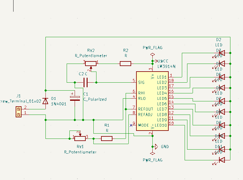
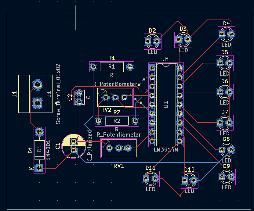
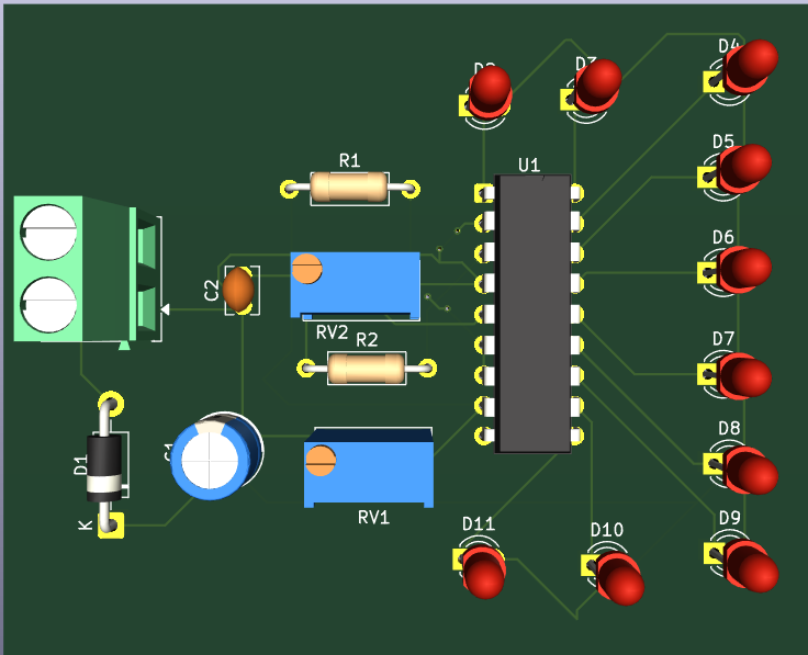
The battery level indicator schematic and PCB layout were designed using KiCad. The 3D model helps visualize the board before manufacturing.
Vijay Kumar
| Qty | Value | Footprint | References |
|---|---|---|---|
| 10 | LED | LED_THT:LED_D3.0mm | D2, D3, D4, D5, D6, D7, D8, D9, D10, D11 |
| 2 | R | Resistor_THT:R_Axial_DIN0207_L6.3mm_D2.5mm_P10.16mm_Horizontal | R1, R2 |
| 2 | R_Potentiometer | Potentiometer_THT:Potentiometer_Bourns_3296W_Vertical | RV1, RV2 |
| 1 | 1N4001 | Diode_THT:D_DO-41_SOD81_P10.16mm_Horizontal | D1 |
| 1 | C | Capacitor_THT:C_Disc_D3.8mm_W2.6mm_P2.50mm | C2 |
| 1 | C_Polarized | Capacitor_THT:CP_Radial_D6.3mm_P2.50mm | C1 |
| 1 | LM3914N | Package_DIP:DIP-18_W7.62mm | U1 |
| 1 | Screw_Terminal_01x02 | TerminalBlock_Phoenix:TerminalBlock_Phoenix_MKDS-1,5-2-5.08_1x02_P5.08mm_Horizontal | J1 |
Gabouin/LAMPED
A simple, desk-friendly LED “lamp” built around the LM3914 LED driver: a 10‑LED circular array that lights up progressively based on a potentiometer input.


doeygirl93/LM3914-LED-meter
Resoulution week 4 LM3914 IC LED potentier controlled LED meter circut

jeff4444/kicad-projects
An RF remote control encoder PCB using the HT12E serial encoder IC.


It measures 67.5 × 55 mm and has 2 copper layers, 1.6 mm thick.
19 parts, built around the LM3914N-1. The full list of its parts is on this page, with links to each part's symbol and footprint where PCBKit's library has them.
From the vijaykumar994543/Battery-Level-Indicator repository on GitHub, at the commit this page was made from: the board is batterylevelindicator.kicad_pcb and its schematic batterylevelindicator.kicad_sch. PCBKit opens the board in the browser, with nothing to install.
Its repository states no licence, so its author keeps all rights: ask vijaykumar994543 before reusing the design.