


2 layers47 × 49 mm
Audio amplifier
jeff4444/kicad-projects
An RF remote control encoder PCB using the HT12E serial encoder IC.
14 parts

 jeff4444/kicad-projects
An RF remote control encoder PCB using the HT12E serial encoder IC.
Recyclobot is an open-source printed circuit board by jeff4444, from the jeff4444/kicad-projects repository on GitHub. It is a 2-layer board of 49.5 × 48 mm with 19 parts on 16 nets, routed with 96 tracks and 9 vias.
It is built around the LM3914N-1, BC547 and IR204-A-L. Its parts include 11 diodes, 4 resistors, 2 transistors, 1 IC and 1 connector.
An RF remote control encoder PCB using the HT12E serial encoder IC.
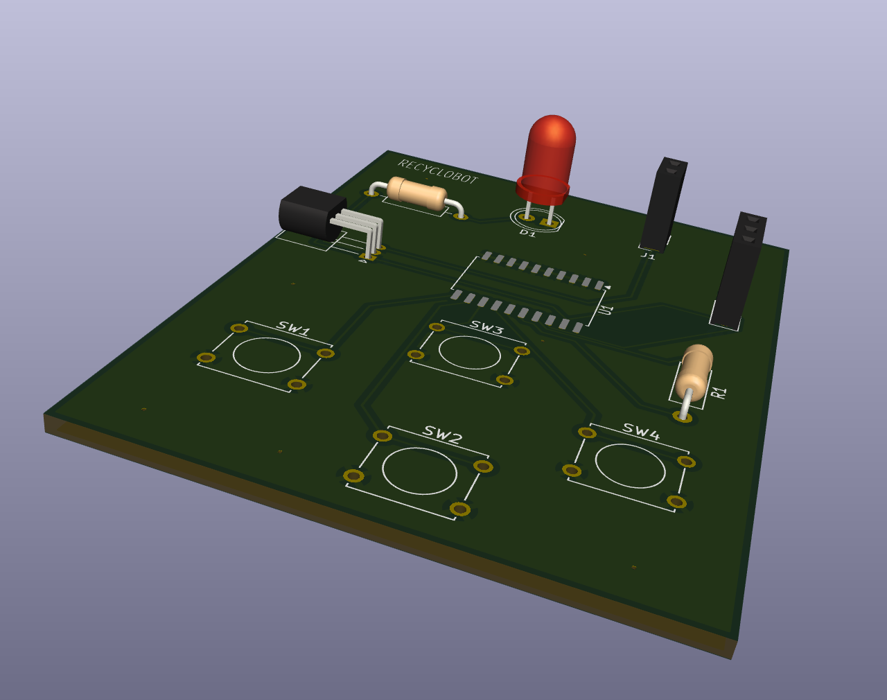
This board serves as the wireless remote control transmitter for the Recyclobot project. It uses the HT12E encoder IC to convert button presses into a serial data stream that can be transmitted wirelessly to the Recyclobot motherboard.
HT12E Serial Encoder IC
LED indicators for status/feedback
Connectors for:
| Parameter | Value |
|---|---|
| Main IC | HT12E |
| Address Bits | 8 (A0-A7) |
| Data Bits | 4 (D0-D3) |
| Package | SOP-20 / DIP-18 |
| Operating Voltage | 2.4V - 12V |
This controller pairs with the Recyclobot Motherboard which uses an HT12D decoder to receive and interpret the transmitted commands.
┌─────────────────┐     RF Signal     ┌─────────────────┐
│   Controller    │ ─────────────────▶│   Motherboard   │
│     (HT12E)     │                   │     (HT12D)     │
│                 │                   │     (L293D)     │
└─────────────────┘                   └─────────────────┘
Remote Robotrecyclobot.kicad_sch - Schematicrecyclobot.kicad_pcb - PCB layoutgerbers/ - Manufacturing files| Qty | Value | Footprint | References |
|---|---|---|---|
| 10 | LED | LED_THT:LED_D3.0mm | D2, D3, D4, D5, D6, D7, D8, D9, D10, D11 |
| 2 | 200 | Resistor_THT:R_Axial_DIN0204_L3.6mm_D1.6mm_P7.62mm_Horizontal | R3, R5 |
| 1 | 10k | Resistor_THT:R_Axial_DIN0204_L3.6mm_D1.6mm_P7.62mm_Horizontal | R4 |
| 1 | 2.2K | Resistor_THT:R_Axial_DIN0204_L3.6mm_D1.6mm_P7.62mm_Horizontal | R1 |
| 1 | BC547 | Package_TO_SOT_THT:TO-92_Inline | Q3 |
| 1 | BPW40 | LED_THT:LED_D5.0mm_Clear | Q1 |
| 1 | Conn_01x02_Socket | Connector_PinSocket_2.54mm:PinSocket_1x02_P2.54mm_Vertical | J1 |
| 1 | IR204A | LED_THT:LED_D3.0mm_IRBlack | D1 |
| 1 | LM3914N | Package_DIP:DIP-18_W7.62mm | U1 |
jeff4444/kicad-projects
An RF remote control encoder PCB using the HT12E serial encoder IC.

jeff4444/kicad-projects
An RF remote control encoder PCB using the HT12E serial encoder IC.

jeff4444/kicad-projects
An RF remote control encoder PCB using the HT12E serial encoder IC.


Gabouin/LAMPED
A simple, desk-friendly LED “lamp” built around the LM3914 LED driver: a 10‑LED circular array that lights up progressively based on a potentiometer input.


doeygirl93/LM3914-LED-meter
Resoulution week 4 LM3914 IC LED potentier controlled LED meter circut


It measures 49.5 × 48 mm and has 2 copper layers, 1.6 mm thick.
19 parts, built around the LM3914N-1, BC547 and IR204-A-L. The full list of its parts is on this page, with links to each part's symbol and footprint where PCBKit's library has them.
From the jeff4444/kicad-projects repository on GitHub, at the commit this page was made from: the board is proximity_sensor/recyclobot.kicad_pcb and its schematic FSO/Receiver board/Circuit.kicad_sch. PCBKit opens the board in the browser, with nothing to install.
Its repository states no licence, so its author keeps all rights: ask jeff4444 before reusing the design.