6 layers45 × 75 mm

 vigneshuw/aems1
Autonomous Energy Monitoring System (AEMS)
EnergyMonitoringSystem is an open-source printed circuit board by vigneshuw, from the vigneshuw/aems repository on GitHub. It is an 8-layer board of 200 × 115 mm with 297 parts on 396 nets, routed with 3,731 tracks and 917 vias.
It is built around the STM32H745ZGT6, ADM2565EBRNZ and BLUENRG-M2SA, with the LAN8742A-CZ-TR, TSV911ILT and ADS131M08IRSNR among its other parts. Its parts include 106 resistors, 100 capacitors, 16 ICs, 14 connectors and 12 diodes. It belongs with the STM32 boards of this library.


KiCad design for the AEMS v2 data-acquisition board: a custom, multi-channel energy-monitoring front end built around the ADS131M08 ADC and the STM32H745 dual-core MCU. This is the hardware layer of the Autonomous Energy Monitoring System and is designed to be reproduced, modified, and manufactured by others.
The KiCad project root is EnergyMonitoringSystem.kicad_pro.
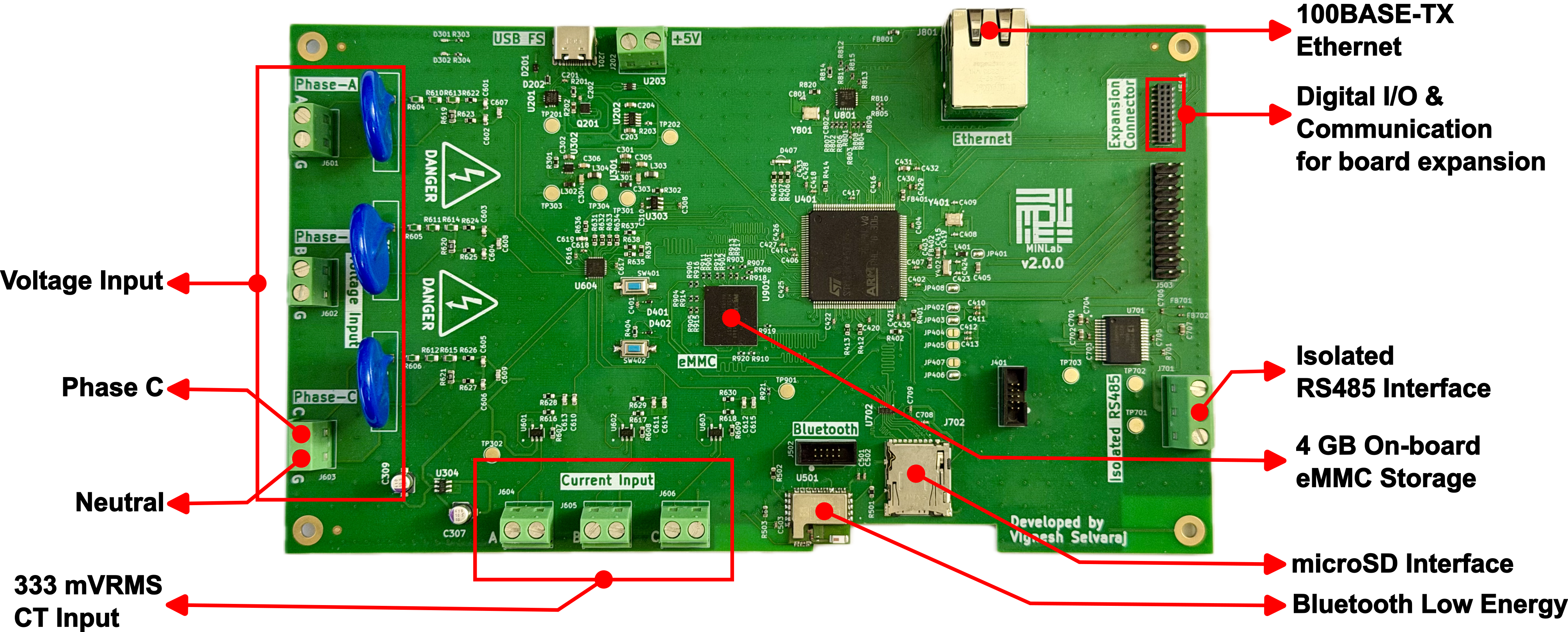
The board acquires multi-channel voltage and current signals at a high, simultaneous sampling rate, digitizes them through the ADS131M08 analog front end, and hands the data to the STM32H745 for on-board logging and network streaming.
Key design features:
DesignSummary/.The current firmware/host workflows use a 6-channel acquisition mask (0x3F) — three voltage and three current channels.
Input voltage topology: the present design is validated for its rated direct-measurement input topology. Measuring higher line-to-line service voltages (e.g. 480 V L-L) exceeds the on-board MOV continuous ratings and requires an updated MOV surge protector (upto a certain voltage level) or external potential transformer. This is consistent with the modular design intent and is tracked under
FutureUpdates/.
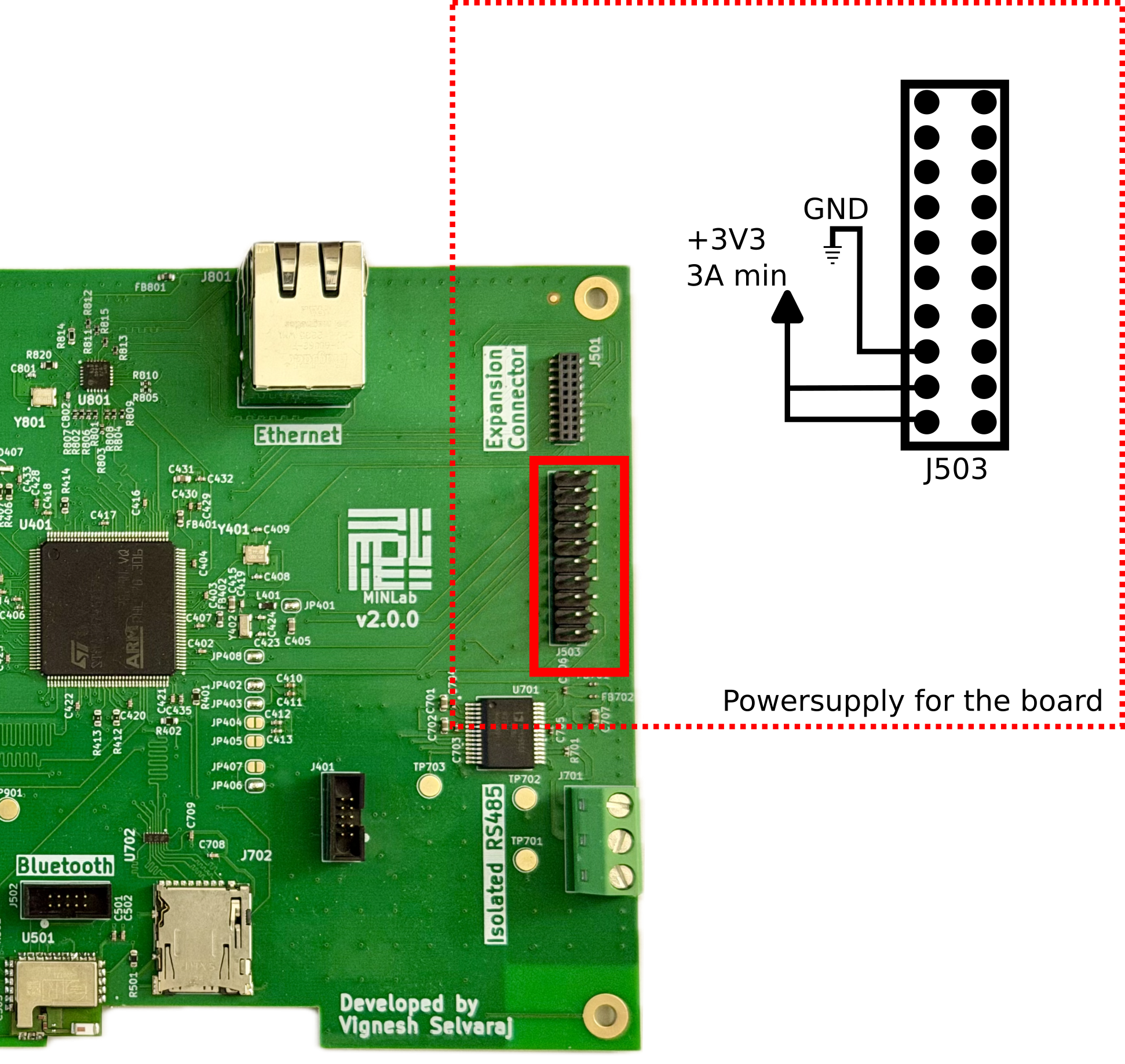
Temporarily, due to a design issue, the board needs to be powered on as shown in the figure below. This design issue will be fixed in the next hardware version.
hardware/
├── EnergyMonitoringSystem.kicad_pro   KiCad project
├── EnergyMonitoringSystem.kicad_sch   Root schematic
├── EnergyMonitoringSystem.kicad_pcb   PCB layout
├── *.kicad_sch                        Hierarchical sheets (see below)
├── CustomLibs/                        Project symbol/footprint libraries
│   ├── EMS.kicad_sym                  Custom symbols
│   ├── EMS.pretty/                    Custom footprints
│   └── Downloaded/                    Third-party part libs (ADS131M08, MOV, op-amps, …)
├── LTSpiceSimulation/                 Analog front-end simulations (CT op-amp, rough studies)
├── Datasheets/                        Component reference material
├── ApplicationNotes/                  ST H7 hardware development notes
├── DesignSummary/                     Stackup, impedance control, interactive BOM
├── Manufacturing/PCBWay/              Fabrication + assembly outputs (Gerbers, drill, BOM, CPL)
└── FutureUpdates/Planned/ Planned revisions (front-end isolation, etc.)The design is hierarchical. The main functional sheets are:
| Sheet | Function |
|---|---|
adc | ADS131M08 analog front end and signal conditioning |
uC / uCMain | STM32H745 microcontroller and support |
ethernet | Ethernet PHY (LAN8742) and magnetics |
poe | Ethernet input (No PoE setup currently) |
vr | Voltage regulation / power rails |
emmc | eMMC storage |
sd_card | SD card interface |
usb | USB interface |
bm | Bluetooth (BlueNRG) module |
DesignSummary/ibom.html in a browser
for a searchable, click-to-highlight BOM with board placement.Manufacturing/PCBWay/EnergyMonitoringSystem.kicad_pcb/PCBWay_bom.csv
and PCBWay_positions.csv (component placement / CPL).Ready-to-fabricate outputs (generated for PCBWay) are in
Manufacturing/PCBWay/ or you generated your own from the KiCAD project:
F_Cu, B_Cu, In1..In6_Cu, mask, paste, silkscreen, edge cuts)PTH, NPTH)PCBWay_bom.csv (BOM) and PCBWay_positions.csv (pick-and-place)PCBWay_netlist.ipc (IPC-356 netlist)DesignRequirements.pdf and Jump-SolderBridges.png (assembly notes)Stackup and impedance targets are documented in DesignSummary/
(CurrentStackup.png, PCBWay Stackup.png, and the ImpedanceControl *.png exports).
To regenerate outputs, open EnergyMonitoringSystem.kicad_pcb in KiCad and re-plot Gerbers/drill
and re-export the BOM/placement.
CustomLibs/ are referenced via the
project-local sym-lib-table / fp-lib-table, so the project should open self-contained.Planned hardware revisions are tracked in FutureUpdates/Planned/,
including improved analog front-end isolation and higher line-to-line voltages.
Hardware licensing is being finalized as part of the open-hardware release; see the top-level LICENSE. Please contact the authors before redistributing the design files until the final license is committed.
For system context, firmware, and host software, see the top-level README.
| Qty | Value | Footprint | References |
|---|---|---|---|
| 36 | 100n | Capacitor_SMD:C_0402_1005Metric | C201, C202, C401, C402, C403, C404, C407, C414, C416, C417, C418, C420, C421, C422, C425, C426 +20 |
| 11 | 10u | Capacitor_SMD:C_0603_1608Metric | C203, C204, C301, C302, C405, C415, C431, C701, C702, C707, C805 |
| 10 | 10p | Capacitor_SMD:C_0603_1608Metric | C601, C602, C603, C604, C605, C606, C610, C611, C612, C619 |
| 10 | 22R | Resistor_SMD:R_0402_1005Metric | R911, R912, R913, R914, R915, R916, R917, R918, R919, R920 |
| 10 | 47k | Resistor_SMD:R_0402_1005Metric | R901, R902, R903, R904, R905, R906, R907, R908, R909, R921 |
| 10 | TestPoint | TestPoint:TestPoint_Pad_D3.0mm | TP201, TP202, TP301, TP302, TP303, TP304, TP701, TP702, TP703, TP901 |
| 9 | 1k | Resistor_SMD:R_0603_1608Metric | R405, R406, R407, R622, R623, R624, R625, R626, R627 |
| 9 | 330k | Resistor_SMD:R_0805_2012Metric | R604, R605, R606, R610, R611, R612, R613, R614, R615 |
| 9 | 33R | Resistor_SMD:R_0603_1608Metric | R412, R413, R414, R631, R632, R633, R634, R635, R636 |
| 8 | 10k | Resistor_SMD:R_0402_1005Metric | R803, R806, R807, R808, R810, R816, R817, R910 |
| 8 | 2u2 | Capacitor_SMD:C_0402_1005Metric | C412, C413, C428, C435, C501, C902, C904, C906 |
| 8 | 49R9 | Resistor_SMD:R_0402_1005Metric | R408, R409, R410, R411, R811, R812, R813, R815 |
| 7 | 1u | Capacitor_SMD:C_0402_1005Metric | C308, C310, C406, C429, C616, C617, C807 |
| 7 | Screw_Terminal_01x02 | TerminalBlock_Phoenix:TerminalBlock_Phoenix_MKDS-1,5-2-5.08_1x02_P5.08mm_Horizontal | J202, J601, J602, J603, J604, J605, J606 |
| 6 | 10k | Resistor_SMD:R_0603_1608Metric | R201, R404, R607, R608, R609, R637 |
| 6 | 5p6 | Capacitor_SMD:C_0402_1005Metric | C408, C409, C423, C424, C801, C802 |
| 6 | 6800p | Capacitor_SMD:C_0603_1608Metric | C607, C608, C609, C613, C614, C615 |
| 6 | Fiducial | Fiducial:Fiducial_1mm_Mask2mm | FM201, FM202, FM203, FM204, FM205, FM206 |
| 5 | PESD3V3L1BA,115 | EMS:PESD3V3L1BA_115-SOD-323-2 | D403, D404, D405, D406, D408 |
| 5 | SolderJumper_2_Bridged | Jumper:SolderJumper-2_P1.3mm_Open_RoundedPad1.0x1.5mm | JP401, JP402, JP403, JP406, JP408 |
| 4 | 0u1 | Capacitor_SMD:C_0402_1005Metric | C703, C704, C705, C706 |
| 4 | 100k | Resistor_SMD:R_0603_1608Metric | R301, R302, R638, R639 |
| 4 | 22R | Resistor_SMD:R_0603_1608Metric | R401, R402, R403, R502 |
| 4 | 33R | Resistor_SMD:R_0402_1005Metric | R801, R802, R804, R805 |
| 4 | 47u | Capacitor_SMD:C_0603_1608Metric | C303, C304, C305, C306 |
| 4 | MountingHole_Pad | MountingHole:MountingHole_3.2mm_M3_Pad | H201, H202, H203, H204 |
| 3 | 15k | Resistor_SMD:R_0603_1608Metric | R616, R617, R618 |
| 3 | 2k | Resistor_SMD:R_0603_1608Metric | R628, R629, R630 |
| 3 | 2u2 | Inductor_SMD:L_0603_1608Metric | L301, L302, L401 |
| 3 | 750R | Resistor_SMD:R_0805_2012Metric | R619, R620, R621 |
| 3 | FerriteBead | Inductor_SMD:L_0603_1608Metric | FB401, FB402, FB801 |
| 3 | R_Variable | EMS:B72220S0271K101 | R601, R602, R603 |
| 3 | SolderJumper_2_Open | Jumper:SolderJumper-2_P1.3mm_Open_RoundedPad1.0x1.5mm | JP404, JP405, JP407 |
| 3 | TSV911ILT | EMS:TSV911ILT_SOT23-5 | U601, U602, U603 |
| 2 | 0R | Resistor_SMD:R_0603_1608Metric | R820, R922 |
| 2 | 10u | Inductor_SMD:L_0805_2012Metric | L303, L304 |
| 2 | 10u | EMS:10SVPS10M | C307, C309 |
| 2 | 120R | Resistor_SMD:R_0402_1005Metric | R203, R701 |
| 2 | 220R | Resistor_SMD:R_0402_1005Metric | R303, R304 |
| 2 | 270R | Resistor_SMD:R_0603_1608Metric | R818, R819 |
| 2 | 4u7 | Capacitor_SMD:C_0402_1005Metric | C410, C411 |
| 2 | Conn_02x05_Counter_Clockwise | EMS:62701021621 | J401, J502 |
| 2 | Crystal_GND24 | EMS:NX3225SA25000MSTDCSR6 | Y401, Y801 |
| 2 | Danger | LOGO | G***, G*** |
| 2 | ESDALC6V1-1M2 | EMS:ESDALC6V11M2 | D401, D402 |
| 2 | FerriteBead | EMS:BLM15HD182SN1D | FB701, FB702 |
| 2 | LED | LED_SMD:LED_0402_1005Metric | D301, D302 |
| 2 | ST1PS02CQTR | EMS:ST1PS02CQTR | U301, U302 |
| 2 | SW_Push | Button_Switch_SMD:SW_SPST_CK_RS282G05A3 | SW401, SW402 |
| 1 | 12k1 | Resistor_SMD:R_0603_1608Metric | R814 |
| 1 | 1k5 | Resistor_SMD:R_0402_1005Metric | R809 |
| 1 | 1n | Capacitor_SMD:C_0402_1005Metric | C812 |
| 1 | 220n | Capacitor_SMD:C_0402_1005Metric | C618 |
| 1 | 220p | Capacitor_SMD:C_0402_1005Metric | C419 |
| 1 | 2k7 | Resistor_SMD:R_0603_1608Metric | R202 |
| 1 | 32.768KHz | Crystal:Crystal_SMD_3215-2Pin_3.2x1.5mm | Y402 |
| 1 | 470p | Capacitor_SMD:C_0402_1005Metric | C806 |
| 1 | 47k | Resistor_SMD:R_0603_1608Metric | R501 |
| 1 | 4k7 | Resistor_SMD:R_0603_1608Metric | R503 |
| 1 | ADM2565EBRNZ | EMS:ADM2565EBRNZ-SOIC-28 | U701 |
| 1 | ADS131M08IRSNR | EMS:ADS131M08IRSNR-QFN40 | U604 |
| 1 | BAT30KFILM | EMS:BAT30KFILM | D202 |
| 1 | BLUENRG-M2SA | EMS:BLUENRG-M2SA | U501 |
| 1 | CLP-110-02-G-D | EMS:CLP-110-02-XXX-D | J501 |
| 1 | Conn_02x08_Counter_Clockwise | Connector_PinHeader_2.54mm:PinHeader_2x10_P2.54mm_Vertical | J503 |
| 1 | DM3AT-SF-PEJM5_40_ | EMS:DM3ATSFPEJM540 | J702 |
| 1 | EMIF06-MSD02N16 | EMS:EMIF06-MSD02N16 | U702 |
| 1 | ESDA7P60-1U1M | EMS:ESDA7P60-1U1M | D201 |
| 1 | LAN8742A-CZ-TR | EMS:LAN8742A-CZ-TR_QFN50 | U801 |
| 1 | LDLN025M12R | EMS:LDLN025M12R-SOT-23-5 | U303 |
| 1 | LED_RAGB | LED_SMD:LED_Kingbright_APFA3010_3x1.5mm_Horizontal | D407 |
| 1 | LM2664M6_NOPB | EMS:LM2664M6_NOPB-SOT-23-6 | U304 |
| 1 | MINLab | LOGO | G*** |
| 1 | MX52LM04A11XSI | EMS:MX52LM04A11XSI_BGA153 | U901 |
| 1 | SI-60062-F | EMS:Connector-SI60062F | J801 |
| 1 | STEF05SGR | EMS:STEF05SGR-TSOT23-8L | U202 |
| 1 | STL6N3LLH6 | EMS:STL6N3LLH6 | Q201 |
| 1 | STM32H745ZGT6 | EMS:STM32H745ZGT6_LQFP144 | U401 |
| 1 | Screw_Terminal_01x03 | TerminalBlock_Phoenix:TerminalBlock_Phoenix_MKDS-1,5-3-5.08_1x03_P5.08mm_Horizontal | J701 |
| 1 | TCPP01-M12 | EMS:TCPP01-M12-QFN-12L | U201 |
The 295 most common of 297 parts.
It measures 200 × 115 mm and has 8 copper layers, 1.61 mm thick.
297 parts, built around the STM32H745ZGT6, ADM2565EBRNZ, BLUENRG-M2SA and LAN8742A-CZ-TR. The full list of its parts is on this page, with links to each part's symbol and footprint where PCBKit's library has them.
From the vigneshuw/aems repository on GitHub, at the commit this page was made from: the board is hardware/EnergyMonitoringSystem.kicad_pcb and its schematic hardware/EnergyMonitoringSystem.kicad_sch. PCBKit opens the board in the browser, with nothing to install.
Its repository states no licence, so its author keeps all rights: ask vigneshuw before reusing the design.

bradencamp/ECE-Lab-USB-MultiTool
This USB Multi-function Laboratory Instrument will be inexpensive and therefore less capable than the AD2 or ADALM 2000 while still fulfilling the requirements for most laboratory exercises in the undergraduate ECE…

jdotw/OpInst-Bass-1
Three-voice analog synth with a digital control surface using CEM3340, AS3320 and similar discrete analog components.


neuroidss/FreeEEG32-alpha131
https://hackaday.io/project/181683-freeeeg32-alpha131