2 layers45.2 × 82 mm
Invertor
victorstoica114/Invertor_board
This repository contains an ESP-IDF firmware for an ESP32 board that bridges, translates, decodes, and exposes battery/inverter communication over CAN and RS485.
8 parts1

 victorstoica114/Invertor_board1
This repository contains an ESP-IDF firmware for an ESP32 board that bridges, translates, decodes, and exposes battery/inverter communication over CAN and RS485.
Invertor is an open-source printed circuit board by victorstoica114, from the victorstoica114/Invertor_board repository on GitHub. It is a 2-layer board of 110 × 82 mm with 151 parts on 104 nets, routed with 1,283 tracks and 271 vias.
It is built around the ESP32-C6-WROOM-1-N8, RS485 and MCP16311-E/MS, with the TPD2S017DBV and ESDA5V3L among its other parts. Its parts include 49 capacitors, 40 resistors, 12 diodes, 10 fuses and 7 ICs. It belongs with the interfaces and adapters boards and the ESP32 and RISC-V boards of this library.


This repository contains an ESP-IDF firmware for an ESP32 board that bridges, translates, decodes, and exposes battery/inverter communication over CAN and RS485.
The project is used as a practical protocol bridge between BMS and inverter, with runtime configuration through a web UI.
See also: CHANGELOG.md
CAN protocol implementation backlog: docs/can_protocols.md
8MB flash)idf.py set-target esp32c67MB factory app partition, no OTA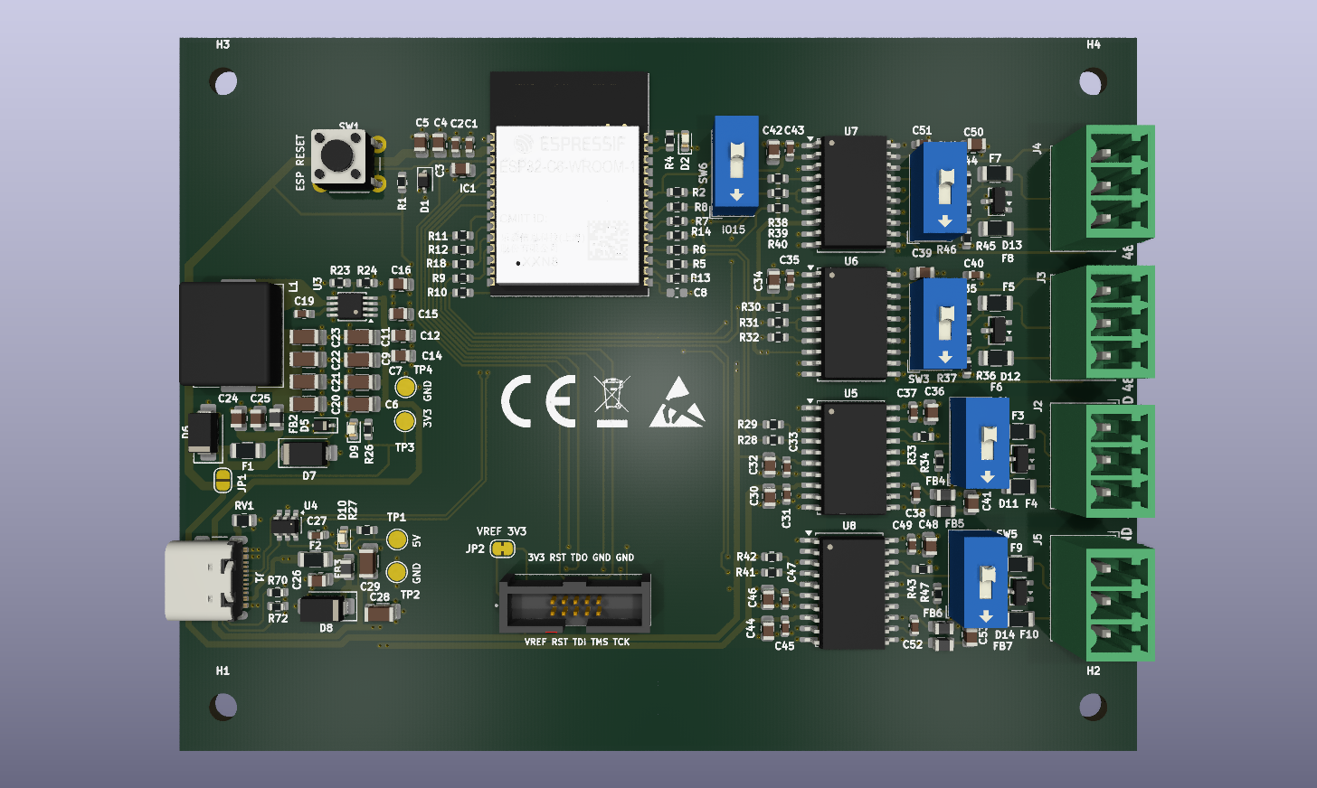
Board schematic: Kicad project/Invertor_main_board/Schematic.pdf
Main goals:
Implemented / available:
RS485_GROWATT BMS polling/decoding (Modbus) + queue publish, including JK UART profile 006 cell voltages and Growatt warning/error bitsJKBMS_MODBUS BMS polling/decoding (Modbus) + rich snapshot, with 9600 and 115200 RS485 variantsJKBMS_RS485_NATIVE experimental BMS polling/decoding (4E 57 native RS485 read-all frames) + rich snapshotPACE_RS485_MODBUS_V1.3 BMS polling/decoding (Modbus) + rich snapshotVOLTRONIC_MODBUS BMS polling/decoding for JK UART profile 007 - Voltronic_Inverter_and_BMS_485 + rich snapshotCHINA_TOWER_MODBUS BMS polling/decoding for JK UART profile 008 - China tower shared battery cabinet V2.0 + pack/cell/temperature snapshotWOW_MODBUS BMS polling/decoding for JK UART profile 009 - WOW_RS485_Modbus_V1.3 + PACE-compatible pack/cell/temperature snapshotDALY_RS485 BMS polling/decoding for the Daly proprietary RS485 protocol + rich snapshotDALY_CAN BMS polling/decoding for the Daly proprietary CAN protocolGROWATT inverter CAN sender (publishes the main low-voltage Growatt CAN frame set from the shared battery model)CAN_GROWATT | CAN_PYLON | CAN_GOODWE | CAN_SOFAR | CAN_SMA | CAN_VICTRON -> RS485_GROWATT translator (main/protocols/rs485_growatt/rs485_growatt_bridge.c)RS485_JKBMS -> RS485_GROWATT translator (JKBMS_MODBUS, JKBMS_MODBUS_115200, and JKBMS_RS485_NATIVE)RS485_WOW -> RS485_GROWATT translator/responder, intended for JK UART profile 009 - WOW_RS485_Modbus_V1.3RS485_JKBMS -> CAN_GROWATT translator/sender (JKBMS_MODBUS, JKBMS_MODBUS_115200, and JKBMS_RS485_NATIVE), preserving JK all-cell telemetry while publishing Growatt CAN inverter framesRS485_JKBMS -> RS485_PYLON translator/responder (JKBMS_MODBUS, JKBMS_MODBUS_115200, and JKBMS_RS485_NATIVE)RS485_GROWATT -> RS485_PYLON translator/responder, intended for JK UART profile 006 - Growatt_BMS_RS485_Protocol_1xSxxP_ESS_Rev2.01RS485_PACE -> RS485_PYLON translator/responderRS485_VOLTRONIC -> RS485_PYLON translator/responder, intended for JK UART profile 007 - Voltronic_Inverter_and_BMS_485RS485_CHINA_TOWER -> RS485_PYLON translator/responder, intended for JK UART profile 008 - China tower shared battery cabinet V2.0RS485_WOW -> RS485_PYLON translator/responder, intended for JK UART profile 009 - WOW_RS485_Modbus_V1.3RS485_DALY -> RS485_PYLON translator/responderRS485_DALY -> CAN_PYLON translator/sender, field-tested as Daly RS485 on RS485_1 to EASUN Pylon CAN on CAN2RS485_PYLON -> CAN_PYLON translator/sender, field-tested as JK Pylon RS485 on RS485_1 to Pylon CAN inverter output on CAN2RS485_PYLON -> CAN_GROWATT translator/sender, using the Pylon RS485 source poller and Growatt CAN sender on the selected CAN inverter portDALY_CAN -> RS485_PYLON translator/responderRS485_PYLON <-> RS485_PYLON bridge/responder, including the RS485_PYLON_115200 variantCAN_PYLON -> RS485_PYLON synthetic responder/bridge, including the RS485_PYLON_115200 variantJKBMS_CAN_250K -> RS485_PYLON synthetic responder/bridge for JK app profile 000 - JK BMS CAN Protocol (250K) V2.0CAN_DEYE -> RS485_PYLON synthetic responder/bridge for JK app profile 001 - Deye Low-voltage hybrid inverter CANCAN_PYLON -> CAN_PYLON direct forward mode for split CAN ports, field-tested as JKBMS Pylon CAN on CAN1 -> EASUN Pylon CAN on CAN2Fake Inverter Data override for inverter-facing synthetic routes, Pylon RS485 passthrough, and Pylon CAN forward framesDual-BMS configuration and current limitations are documented in docs/dual_bms.md.
Partially implemented / scaffold:
PROTOCOL_ID_PYLON BMS task (pylon_bms_task.c) remains a scaffold placeholder; the inverter side has an active CAN_PYLON sender and RS485 Pylon routes are handled by the dedicated bridge/responderCAN_SOFAR, CAN_SMA, CAN_VICTRON have protocol IDs and register-map headers, but no dedicated full task pipeline yetCAN_DEYE has active CAN decode path, but is not currently in the dedicated CAN -> RS485_GROWATT special-route selectorDALY_CAN has a native poller and RS485_PYLON synthetic responder route, but the field BMS tested on 2026-05-30 did not ACK CAN traffic on either CAN portEASUN_PYLON_24V_DIAG_SENDER_ENABLE=0)Current bridge-mode route matrix:
| Route | Condition | Status |
|---|---|---|
| CAN -> RS485_GROWATT translator | bms_line=CAN, inv_line=RS485, inv_protocol=RS485_GROWATT, bms_protocol in {CAN_GROWATT,CAN_PYLON,CAN_GOODWE,CAN_SOFAR,CAN_SMA,CAN_VICTRON} | Active |
| RS485_JKBMS -> RS485_GROWATT translator | bms_line=RS485, inv_line=RS485, bms_protocol in {JKBMS_MODBUS,JKBMS_MODBUS_115200,JKBMS_RS485_NATIVE}, inv_protocol=RS485_GROWATT | Active for Modbus; native is experimental |
| RS485_WOW -> RS485_GROWATT translator | bms_line=RS485, inv_line=RS485, bms_protocol=WOW_MODBUS, inv_protocol=RS485_GROWATT | Active; covers JK UART profile 009 with the PACE-compatible WOW map |
| RS485_JKBMS -> CAN_GROWATT translator | bms_line=RS485, inv_line=CAN, bms_protocol in {JKBMS_MODBUS,JKBMS_MODBUS_115200,JKBMS_RS485_NATIVE}, inv_protocol=CAN_GROWATT | Active; preferred when the web/API must show JK all-cell voltages while the inverter receives Growatt CAN |
| RS485_JKBMS -> RS485_PYLON translator | bms_line=RS485, inv_line=RS485, bms_protocol in {JKBMS_MODBUS,JKBMS_MODBUS_115200,JKBMS_RS485_NATIVE}, inv_protocol in {RS485_PYLON,RS485_PYLON_115200} | Active for Modbus; native is experimental |
| RS485_GROWATT -> RS485_PYLON translator | bms_line=RS485, inv_line=RS485, bms_protocol=RS485_GROWATT, inv_protocol=RS485_PYLON | Active; covers JK UART profile 006 |
| RS485_GROWATT -> CAN_PYLON translator | bms_line=RS485, inv_line=CAN, bms_protocol=RS485_GROWATT, inv_protocol=CAN_PYLON | Active; field-tested with Seplos selector 10 (Growatt SPF), signed current and all 16 cell voltages |
| RS485_PACE -> RS485_PYLON translator | bms_line=RS485, inv_line=RS485, bms_protocol=PACE_RS485_MODBUS, inv_protocol=RS485_PYLON | Active |
| RS485_VOLTRONIC -> RS485_PYLON translator | bms_line=RS485, inv_line=RS485, bms_protocol=VOLTRONIC_MODBUS, inv_protocol=RS485_PYLON | Active; covers JK UART profile 007 |
| RS485_CHINA_TOWER -> RS485_PYLON translator | bms_line=RS485, inv_line=RS485, bms_protocol=CHINA_TOWER_MODBUS, inv_protocol=RS485_PYLON | Active; covers JK UART profile 008 |
| RS485_WOW -> RS485_PYLON translator | bms_line=RS485, inv_line=RS485, bms_protocol=WOW_MODBUS, inv_protocol=RS485_PYLON | Active initial implementation; covers JK UART profile 009 with PACE-compatible map |
| RS485_DALY -> RS485_PYLON translator | bms_line=RS485, inv_line=RS485, bms_protocol=DALY_RS485, inv_protocol=RS485_PYLON | Active |
| RS485_DALY -> CAN_PYLON translator | bms_line=RS485, inv_line=CAN, bms_protocol=DALY_RS485, inv_protocol=CAN_PYLON | Active; field-tested with EASUN 24V |
| RS485_PYLON -> CAN_PYLON translator | bms_line=RS485, inv_line=CAN, bms_protocol in {RS485_PYLON,RS485_PYLON_115200}, inv_protocol=CAN_PYLON | Active; field-tested with JK Pylon RS485 at 9600 |
| RS485_PYLON -> CAN_GROWATT translator | bms_line=RS485, inv_line=CAN, bms_protocol in {RS485_PYLON,RS485_PYLON_115200}, inv_protocol=CAN_GROWATT | Active; uses the Pylon RS485 source poller and Growatt CAN sender |
| DALY_CAN -> RS485_PYLON translator | bms_line=CAN, inv_line=RS485, bms_protocol=DALY_CAN, inv_protocol=RS485_PYLON | Experimental; protocol task implemented, live CAN link not validated |
| Pylon RS485 bridge | RS485_PYLON<->RS485_PYLON, RS485_PYLON->CAN_PYLON, CAN_PYLON->RS485_PYLON, CAN_DEYE->RS485_PYLON, or JKBMS_CAN_250K->RS485_PYLON, with RS485_PYLON_115200 accepted on RS485 sides | Active |
| Generic orchestrator route | any other valid combination | Active, depends on protocol task maturity |
Modes are selected from runtime settings (mode):
MODE_BRIDGE = 3MODE_FORWARD = 2CAN1->CAN2, RS485_1->RS485_2) with optional decode loggingJKBMS Pylon CAN -> EASUN Pylon CAN, with JKBMS on CAN1, EASUN on CAN2, both at 500 kbit/sFake Inverter Data is enabled, Pylon CAN forward modifies outgoing inverter-facing frames before transmit (0x351, 0x355, 0x356, 0x35C, and 0x373 when present)MODE_SNIFFER = 1Important:
Bridge mode route selection is done in orchestratorStartFromRuntime(...):
CAN -> RS485_GROWATT translator routeRS485_JKBMS -> RS485_GROWATT translator routeRS485_WOW -> RS485_GROWATT translator routeRS485_JKBMS -> RS485_PYLON translator routeRS485_GROWATT -> RS485_PYLON translator routeRS485_PACE -> RS485_PYLON translator routeRS485_VOLTRONIC -> RS485_PYLON translator routeRS485_CHINA_TOWER -> RS485_PYLON translator routeRS485_WOW -> RS485_PYLON translator routeRS485_SEPLOS -> RS485_PYLON translator routeRS485_DALY -> RS485_PYLON translator routeDALY_CAN -> RS485_PYLON translator routePylon RS485 bridge route (RS485_PYLON<->RS485_PYLON, RS485_PYLON->CAN_PYLON, or CAN_PYLON->RS485_PYLON)protocol_id_t based)As of the 2026-05-30 field session, the EASUN inverter CAN path is validated as a split-port forward route.
Bench setup that worked:
PYLON CAN and connected to CAN1.PYLON CAN and connected to CAN2.500 kbit/s.CAN1 -> CAN2.BMS_protocol=PROTOCOL_CAN_PYLON,
Inverter_protocol=PROTOCOL_CAN_PYLON, BMS_PORT=1, Inverter_PORT=2.Observed frames:
0x351, 0x355, 0x356, 0x359,
0x35C, 0x35E, 0x370, and 0x371.0x35E identifies the source as JK-BMS.0x305 [00 00 00 00 00 00 00 00] frames when its CAN
hardware is healthy.Important hardware finding:
Current forwarding rule:
CAN_FORWARD_PYLON_16S_TO_8S_ENABLE=0), even though EASUN is a 24V inverter.16S->8S scaler remains behind the compile-time macro if a
future inverter test proves it is needed.Fake-data behavior:
Fake Inverter Data now affects Pylon CAN forward mode, not only
synthetic bridge/responders.0x355
(SOC/SOH).SOC=0% was field-confirmed to influence EASUN behavior.SOC=0% makes EASUN stop/sleep, CAN TX failures or no-ACK counters on
the inverter-facing bus can be expected during that test./api/fake_bms.As of the 2026-06-03 field session, a JK BMS configured for PYLON RS485
can feed a Pylon CAN inverter path through the bridge.
Bench setup that worked:
PYLON RS485 at 9600 bps and connected to
RS485_1.CAN_PYLON on CAN2.MODE_BRIDGE, PROTOCOL_RS485_PYLON -> PROTOCOL_CAN_PYLON.config.h defaults are set for this bench route when NVS is empty or
invalid. Normal boots load the runtime settings saved by the web UI/API from
NVS.Validated live values:
/api/settings after reboot reported bms_line=RS485,
bms_protocol=RS485_PYLON, bms_port=1, inverter_line=CAN,
inverter_protocol=CAN_PYLON, inverter_port=2./api/telemetry reported fresh RS485_1 / RS485_PYLON data with
SOC=100%, pack voltage around 57.14..57.15 V, cell max/min around
3.573/3.571 V, and Pylon status 0xC0.0x61 and 0x63 Pylon RS485 responses with
chk=OK, followed by Pylon CAN inverter TX on CAN2.0x42 cell-information responses and publish
the full per-cell voltage list when a BMS exposes that frame. The tested JK
PYLON RS485 profile did not expose it: 0x42 with FF, 00, 01, or an
empty payload was rejected on the live 0x02 address with response code
0x04; the other tested Pylon pack addresses did not answer. For this JK
profile the UI/API therefore shows only the 0x61 cell max/min values, not
cells_v[]. Use JKBMS_MODBUS or JKBMS_RS485_NATIVE on the BMS side, plus
an inverter-facing route such as RS485_JKBMS -> CAN_GROWATT, when full cell
voltages are required in telemetry.CID2=0x42; the active probe now tries the aggregate FF request, the
discovered response address, the low address nibble, 01, 00, and an empty
payload. The tested Seplos Pylon profile replied to 0x42 on address 0x12
with an OK frame but no payload for those request forms, so its web/API
telemetry currently remains limited to 0x61 cell max/min values.Implementation details that matter:
0x02 on the tested JK setup) and then keeps using that address instead of
cycling slowly through every candidate address.0x12.0x61 responses can encode the first voltage word as a
raw millivolt-like pack value. The firmware normalizes that value before web
telemetry and Pylon CAN transmission, so 0xDF34 becomes about 57.14 V,
not 571.4 V.PYLON_RS485_SOURCE_STALE_MS is 10000 ms. If the RS485 source disappears,
the Pylon CAN sender stops after this freshness window instead of replaying
stale data.As of the 2026-05-30 field session, the Daly 24V pack can drive the EASUN inverter through the bridge:
RS485_1.PYLON CAN on CAN2.MODE_BRIDGE, PROTOCOL_RS485_DALY -> PROTOCOL_CAN_PYLON.config.h defaults
are now set to the JK Pylon RS485 to Pylon CAN route above.Validated live values:
28.29..28.31 V,
SOC=99.2%, current 0.0 A, charge/discharge enabled, no alarms.CAN2: SOC=99%, pack around 28.29 V, status 0xC0.Important interpretation:
58 V Pylon CAN snapshot on CAN1 was not Daly data. It came from
the old CAN_PYLON -> CAN_PYLON forward setup and should not be used to infer
Daly CAN behavior.Disconnect behavior:
DALY_RS485_SOURCE_STALE_MS is 10000 ms. After that,
the sender stops transmitting and logs Pylon CAN inverter sender has no fresh BMS model yet.As of the 2026-05-24 field session, the Seplos RS485 issue was traced to a hardware-layer requirement: the tested Seplos BMS does not provide RS485 bias resistors on its interface. The bridge hardware used during testing also does not provide enough fail-safe bias on that bus, so the idle RS485 line can float. In that state the firmware sees noise-like bytes or short invalid chunks even though the same Seplos BMS communicates normally with an inverter that provides proper bus bias.
This is a hardware compatibility issue, not primarily a Pylon/Seplos protocol decoder problem.
Observed on the bench:
RS485_PYLON <-> RS485_PYLON, the inverter
sends valid Pylon requests on RS485_2 (0x61 and 0x63), and the firmware
forwards those requests to RS485_1.RS485_1 raw captures after forwarding do not contain a valid Pylon ASCII
frame (~...), a valid Seplos ASCII frame, or a coherent Modbus RTU response.
Captured bytes were mostly 00, FF, 05, EE, and other non-frame data.RS485_1 in ESP-IDF half-duplex mode,
manual direction control, and inverted manual direction control.9600 also did not produce valid
responses; only single-byte or short non-frame raw chunks were captured.0x61, 0x62, and 0x63 Pylon-compatible
responses decode correctly on address 0x12. 0x42 cell-information probes
using FF, the discovered address (12), low nibble (02), 01, 00, and
empty payload returned OK/no-payload frames, so this Seplos Pylon profile did
not expose full per-cell voltages during the field test.Hardware requirement / diagnostic recommendation:
RS485_2 as the known-good inverter side unless the hardware wiring is
intentionally changed.As of the 2026-05-30 field session, DALY_CAN is implemented as a native CAN
poller, but it is not live-validated with the tested Daly BMS.
Protocol assumptions currently used by the firmware:
250 kbit/s.0x18{DataID}{BMS_ID}40.BMS_ID = 1, so the SOC/current/voltage request is
0x18900140.0x18904001.datasheets/daly-can-communications-protocol-v1-0-pr_69416dce77488f5846f10633ac80e389.pdf.Additional compatibility test already tried:
dbus-serialbattery
discussion #561 shows examples such as cansend can0 18950140#.Observed on the bench:
CAN1 and CAN2 were both tested at 250 kbit/s.0x18900140.txErr=128, increasing
txFail/bus error count, rxErr=0, and rxMiss=0.Current interpretation:
JKBMS_MODBUS -> RS485_PYLONFor generic BMS sources such as JKBMS_MODBUS, the synthetic Pylon 0x63 status byte must stay conservative.
What we found during field debugging:
Fake Inverter Data override was activeSOC, and current looked valid0x63 status byteRequired rule:
balance flag into Pylon 0x630xC0 (charge + discharge enabled) instead of 0xE0Why this matters:
balance=1 produced 0xE00xC0 but faulted on 0xE0Implementation reference:
main/protocols/pylon/pylon_rs485_bridge.cbuildCanDerivedInfo63(...)Additional robustness kept in place:
JKBMS cellAvgMv is rejected as a pack-voltage source when it is inconsistent with decoded cell min/max values in the same snapshotDefined in main/config.h:
LINE_CAN = 1LINE_RS485 = 2PROTOCOL_CAN_GROWATT = 1PROTOCOL_RS485_GROWATT = 2PROTOCOL_RS485_PYLON = 3PROTOCOL_CAN_PYLON = 4PROTOCOL_CAN_DEYE = 5PROTOCOL_RS485_JKBMS = 6PROTOCOL_CAN_GOODWE = 7PROTOCOL_CAN_SOFAR = 8PROTOCOL_CAN_SMA = 9PROTOCOL_CAN_VICTRON = 10PROTOCOL_RS485_PACE = 11PROTOCOL_RS485_JKBMS_NATIVE = 12PROTOCOL_RS485_VOLTRONIC = 13PROTOCOL_RS485_CHINA_TOWER = 14PROTOCOL_RS485_WOW = 15PROTOCOL_RS485_JKBMS_115200 = 16PROTOCOL_RS485_PYLON_115200 = 17PROTOCOL_CAN_JKBMS_250K = 18PROTOCOL_RS485_SEPLOS = 19PROTOCOL_RS485_SEPLOS_19200 = 20PROTOCOL_RS485_DALY = 21PROTOCOL_CAN_DALY = 22Baud-rate / bitrate detail:
PROTOCOL_RS485_JKBMS and PROTOCOL_RS485_PYLON use 9600PROTOCOL_RS485_JKBMS_115200 and PROTOCOL_RS485_PYLON_115200 use 115200115200 variants reuse the same protocol decoders/responders; only the selected RS485 port baud changesPROTOCOL_RS485_SEPLOS_19200 uses 19200; PROTOCOL_RS485_SEPLOS and PROTOCOL_RS485_DALY use 9600PROTOCOL_CAN_JKBMS_250K and PROTOCOL_CAN_DALY reinitialize the selected CAN port at 250 kbit/s; other CAN profiles currently default to 500 kbit/sTop-level:
main/ active firmware componentbuild/ ESP-IDF build artifacts (ignored)vendor/ local/vendor files (ignored)Protocol_Tasks/ legacy/auxiliary materialInside main/:
main.capp_main), initializes drivers, mode manager, web taskconfig.h, config.cruntime_settings.h/.cbridge_cfg namespace)orchestrator/modes/decoders/CAN_Decoder cache/snapshot/decodemodbusDecoder stream decoder and register cacheprotocols/Drivers/Web_interface/protocols/rs485_growatt/rs485_growatt_bridge.c/.hold/Active source tree is defined by main/CMakeLists.txt and currently uses:
main/protocols/... (lowercase)main/modes/...main/decoders/...main/orchestrator/...Legacy/cleanup leftovers still present in repo:
main/Protocols/, main/BMS_Protocols/, main/Inverter_Protocols/, main/old/These are useful for reference/history, but are not the primary active implementation path.
main/protocols/growatt/
growatt_bms_task.c: adapter/wrapper over rs485_growatt BMS taskgrowatt_inverter_task.c: active CAN transmit task (0x322)growatt_registers_map.h/.c: register + frame mapping constantsmain/protocols/rs485_growatt/
0x0018, per-cell voltages, cell min/max, Growatt 0x0014 error/protection bits, 0x0022 warning bits, and raw 0x0013 status flags when the BMS exposes themmain/protocols/jkbms_modbus/
0x12A0..0x12A1 is exposed as an alarm/status candidate only; live hardware
has shown stable non-zero values there while the JK display reports no
alarms, so these bits are not propagated to UI protections/alarms/warnings or
inverter-facing alarm masks until a real fault-state capture validates themmain/protocols/jkbms_rs485/
4E 57SOC, SOH fallback, cycles, capacity, per-cell voltages, cell min/max/avg/delta, tube/MOS temperature, battery temperature, box temperature, raw alarm bits, charge/discharge MOS status, and balance statusRS485_JKBMS -> RS485_PYLON and RS485_JKBMS -> RS485_GROWATT bridge-mode translation through the shared battery modelJKBMS_MODBUS at 9600, but does not respond to the native 4E 57 read-all request, so JKBMS_MODBUS remains the recommended setting for that hardwaremain/protocols/pace_modbus/
RS485_PACE -> RS485_PYLON bridge-mode translationmain/protocols/rs485_growatt/
10 (Growatt SPF Modbus RS485 RTU): the web/API exposes all 16 cells and the generic route forwards the battery model to CAN_PYLONmain/protocols/voltronic_modbus/
007 - Voltronic_Inverter_and_BMS_4850x03 reads; the tested Seplos firmware rejects broad reads but answers single-register requests with a 16-bit byte-count response (01 03 00 02 ... CRC)RS485_VOLTRONIC -> RS485_PYLON bridge-mode translation through the shared synthetic Pylon responder pathSOC, voltage/current, capacity, charge/discharge limits/status) and raw protocol flags; the tested Seplos Voltronic profile did not expose per-cell voltages through this mapmain/protocols/china_tower_modbus/
0080x0000 for pack voltage, cell count, SOC, and runtime fields, with per-cell millivolts starting at 0x0009; raw candidate warning/protection/status fields are captured at 0x0019..0x001BRS485_CHINA_TOWER -> RS485_PYLON bridge-mode translation through the shared synthetic Pylon responder pathSOC, all cell voltages, cell min/max/delta, and the three live temperature registers observed in the compact summary block; only MOS, Temp 1, and Temp 2 are labeled for this profile because the exact battery-sensor assignment is not yet confirmed008 are not confirmed yet; non-zero raw candidate warning/protection bits are surfaced as unknown bits until they can be correlated with the JK appmain/protocols/wow_modbus/
009 - WOW_RS485_Modbus_V1.3RS485_WOW -> RS485_PYLON bridge-mode translation through the shared synthetic Pylon responder pathRS485_WOW -> RS485_GROWATT bridge-mode translation through the shared Growatt RS485 responder fed from the universal battery model009 confirmed stable pack, cell, temperature, and Pylon-responder behavior; alert naming remains conservative until more fault-state captures are availablemain/protocols/daly_rs485/
9600SOC, SOH, cycles, capacity, cell extremes, per-cell voltages where exposed, temperature sensors, MOS state, balance state, and failure/status bitsRS485_DALY -> RS485_PYLON bridge-mode translation through the shared synthetic Pylon responder path10smain/protocols/daly_can/
250 kbit/s0x18{DataID}{BMS_ID}40, with BMS_ID=1 on the field hardwareDALY_RS485, so successful CAN telemetry can feed DALY_CAN -> RS485_PYLONmain/protocols/pylon/
pylon_rs485_bridge.c: active bridge/responder for Pylon RS485 routes,
including active BMS-side probing/parsing, optional Pylon 0x42
cell-information decoding when the source exposes it, and
RS485_PYLON -> CAN_PYLON model publicationpylon_can_protocol.c: active CAN snapshot decode for Pylon framespylon_inverter_task.c: active Pylon CAN sender from the shared battery
model for routes such as DALY_RS485 -> CAN_PYLON and
RS485_PYLON -> CAN_PYLONpylon_bms_task.c: scaffold placeholder for future dedicated Pylon BMS taskpylon_registers_map.h: canonical register map headermain/protocols/deye/
deye_can_protocol.c: active CAN snapshot decode for Deye frame setmain/protocols/goodwe|sofar|sma|victron/
If Codex Web (or any contributor) adds a new protocol, use this mandatory layout:
main/protocols/<protocol_name>/main/protocols/<protocol_name>/<protocol_name>_registers_map.hmain/protocols/<protocol_name>/<protocol_name>_registers_map.c<protocol_name>_bms_task.c/.h<protocol_name>_inverter_task.c/.h<protocol_name>_can_protocol.c/.h<protocol_name>_modbus_poller.c/.hMinimum integration checklist (so files are actually used):
main/CMakeLists.txt*_registers_map.h from runtime codemain/config.h (if new ID is needed)main/runtime_settings.cmain/Web_interface/web_interface.cmain/orchestrator/orchestrator.cPACE_RS485_MODBUS_V1.3 -> RS485_PYLON is the reference for how new protocol integrations should look and behave in the web UI/API.
For every new BMS protocol, aim to expose a complete, inspectable telemetry snapshot:
SOC, SOH, cycle count, and capacity fields when the source protocol provides themValidation expectation:
/api/telemetry and the web UI against the vendor/BMS app screenshots or live source dataAvoid temporary UI polish that hides missing decode work. If the source protocol exposes a value, prefer decoding and showing it explicitly; if it is not known yet, show None, -, or a raw diagnostic value instead of fabricating a plausible value.
main/main.cmain/modes/mode_manager.cbridge/forward/sniffermain/orchestrator/orchestrator.cmain/protocols/rs485_growatt/rs485_growatt_bridge.cmain/protocols/pylon/pylon_rs485_bridge.cmain/decoders/CAN_Decoder.cmain/decoders/modbusDecoder.cmain/Web_interface/web_interface.cmain/Web_interface/bridge_compat.cShared data structures:
bms_decoded_packet_t in main/orchestrator/protocol_types.huniversal_battery_model_t in main/protocols/common/universal_battery_model.hbridgeTelemetrySnapshot_t in main/Web_interface/web_bridge_api.hThe ESP32 serves a responsive, dependency-free web UI directly from the
firmware. It is organized into three tabs: Telemetry, Settings, and Logs.
The page refreshes runtime data through the JSON/text endpoints documented in
the next section.
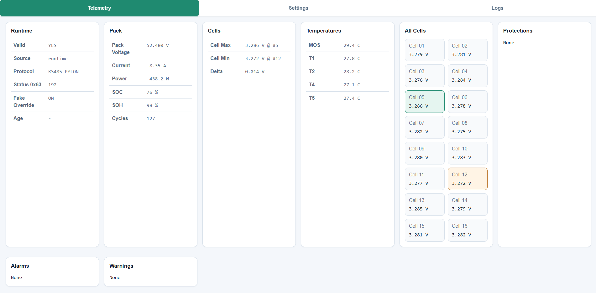
The telemetry view summarizes the active source and protocol, pack voltage, current and power, SOC/SOH, cycle count, cell extrema and delta, temperatures, individual cell voltages, and decoded protections, alarms, and warnings.
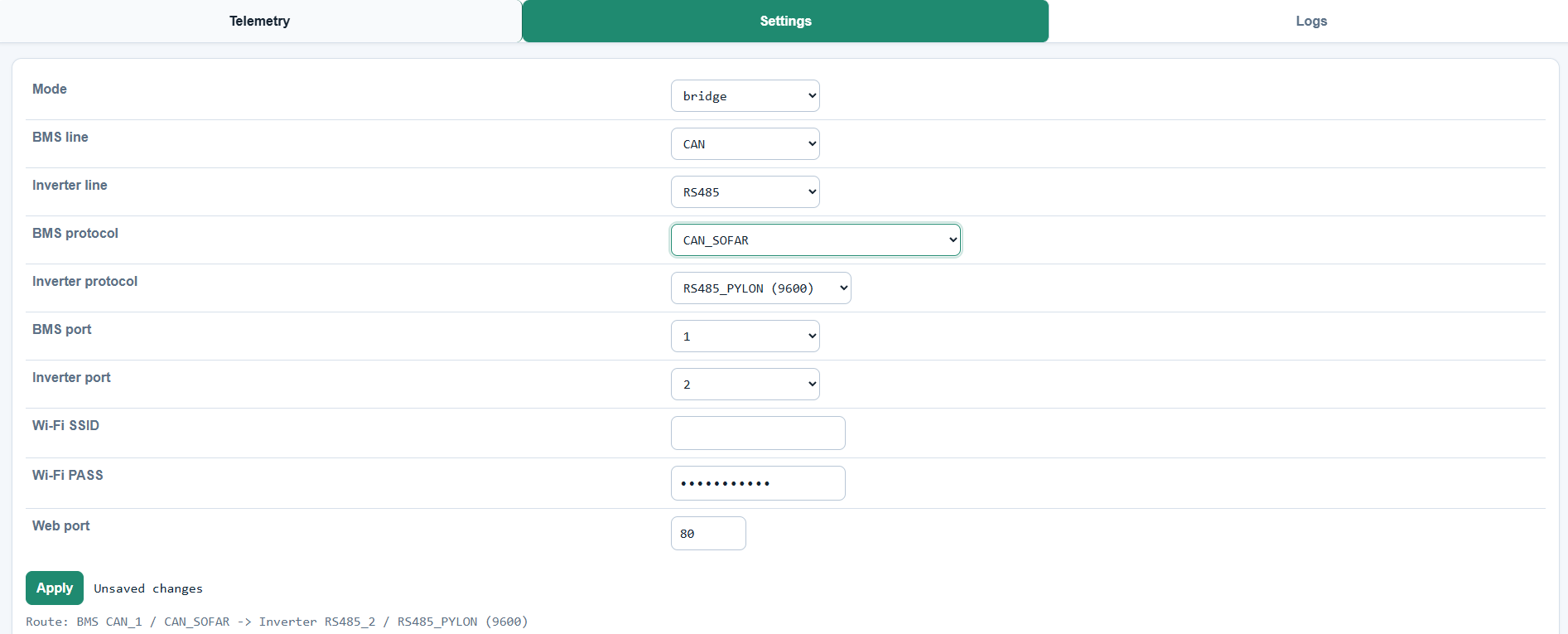
The settings view selects the runtime mode, BMS/inverter lines and protocols,
physical ports, Wi-Fi credentials, and web-server port. Its route preview is
updated before Apply; accepted settings are saved in NVS and applied at
runtime.
The logs view exposes the latest protocol-aware decoded snapshot for field diagnostics, including frame families, cell values, pack data, limits, temperatures, alarms, and protocol status when supplied by the active decoder.
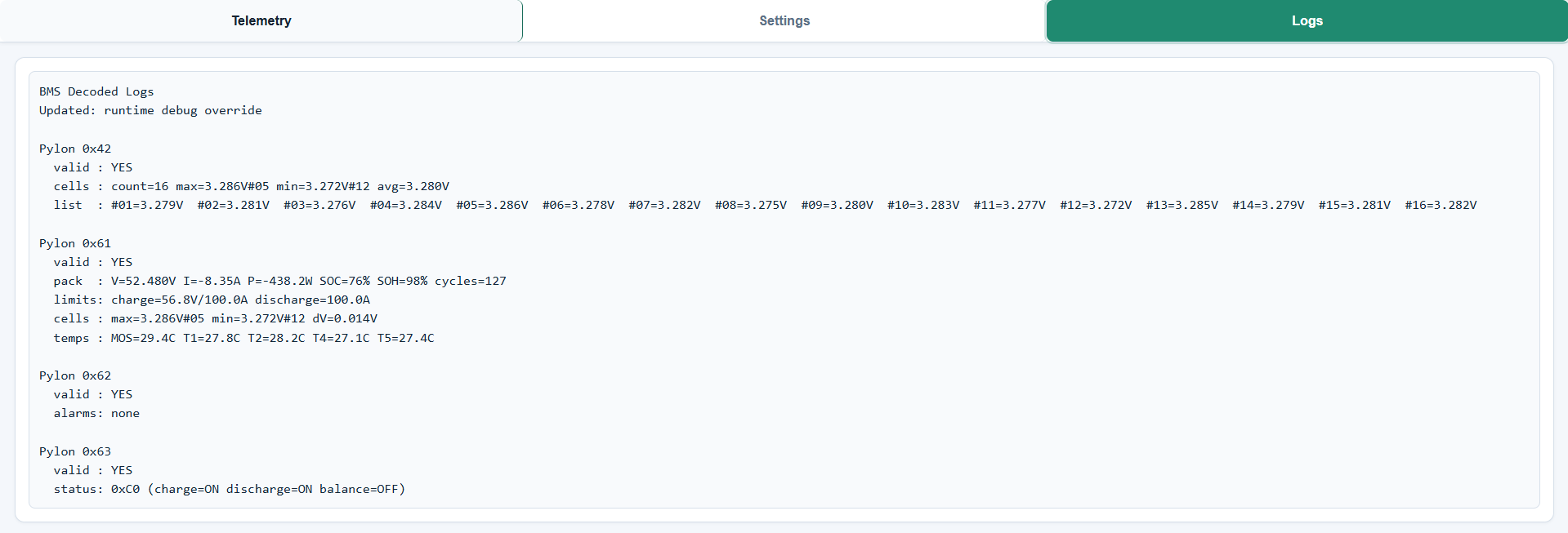
Note: The Telemetry and Logs screenshots use an injected diagnostic dataset so all UI regions are populated. They demonstrate the interface layout and are not a recording of a live BMS/inverter transaction.
Implemented endpoints:
GET /GET /api/telemetryGET /api/settingsPOST /api/settingsGET /api/logsGET /api/fake_bmsPOST /api/fake_bmsRuntime settings are persisted in NVS namespace bridge_cfg.
Optional PulseView/libsigrokdecode helpers live under tools/sigrok/.
Decoder development rule:
this firmware repository is the workbench/source of truth for all in-progress PulseView decoders
develop, test, and refine decoders under tools/sigrok/decoders
copy a decoder to the separate sigrok-pylon-bms-decoders repository only
after it is validated together on captures/hardware and explicitly accepted
for publication
use tools/sigrok/copy-decoder-to-public-repo.ps1 -DecoderName <decoder>
for that publication copy; do not use raw recursive copy commands, because
the helper skips __pycache__ and .pyc artifacts
for live debugging, launch PulseView through
tools/sigrok/start-pulseview.ps1 or the PulseView Workbench Decoders
shortcut so the active local workbench decoder set is used
tools/sigrok/decoders/pylon_rs485/ decodes Pylon-compatible RS485 ASCII frames stacked above the built-in uart decoder.
tools/sigrok/decoders/growatt_rs485/ decodes Growatt-compatible RS485 Modbus RTU frames stacked above the built-in uart decoder, including CRC, request/response register ranges, status/warning/protection fields, and the 0x0071..0x0080 cell-voltage block.
tools/sigrok/decoders/pylon_can/ decodes Pylon-compatible Classic CAN frames directly from a CAN/RXD or digitized CANH/CANL logic capture.
tools/sigrok/decoders/growatt_can/ decodes Growatt-compatible Classic CAN frames directly from a CAN/RXD or digitized CANH/CANL logic capture, including 0x311..0x323 pack, limit, alert, cell, temperature, and metadata frames.
tools/sigrok/decoders/jkbms_modbus/ decodes JK BMS RS485 Modbus poller frames stacked above uart, including the 0x1200..0x12B8 runtime register map used by JKBMS_MODBUS (RS485 Poller, 115200).
tools/sigrok/decoders/jkbms_rs485_native/ decodes JK native binary RS485 frames (4E 57 ...) stacked above uart, including the 0x79 all-cell voltage list, pack values, temperatures, alarm bits, and status flags.
tools/sigrok/decoders/jkbms_can/ decodes JK native CAN V2.0 frames at 250 kbit/s, including 0x02F4, 0x04F4, 0x05F4, 0x07F4, extended 0x18E*28F4 cell-voltage frames, and 0x18F228F4 temperatures.
Typical analyzer settings are 9600 baud, 8N1, LSB-first; line inversion depends on whether the probe is on TTL RX/TX or on the RS485 A/B pair.
For the JK app profile 001 - JK BMS RS485 Modbus V1.0, use the jkbms_modbus decoder at 115200 8N1; for profile 013, use the same decoder at 9600 8N1.
The Pylon RS485 decoder validates Pylon length/checksum fields and decodes common 0x61, 0x62, and 0x63 payloads, including the important 0x63 status byte (0xC0 = charge/discharge enabled, balance off).
For JK Modbus captures, use the local register table in main/protocols/jkbms_modbus/jkbms_modbus_registers_map.h; for JK native RS485 captures, use the binary data-ID map in the decoder/firmware parser instead of treating the bytes as Modbus registers.
See tools/sigrok/README.md for installation and PulseView usage.
Use ESP-IDF v6.0.1 and target esp32c6.
Before the first local build, create a private secrets file for your Wi-Fi credentials:
cp main/secrets.example.h main/secrets.hTypical shell flow:
. /path/to/esp-idf/export.sh
idf.py set-target esp32c6
idf.py build
idf.py -p <PORT> flash monitor
Notes:
project-nameidf_build_set_property(MINIMAL_BUILD ON)8MB--flash-size 8MBpartitions_8mb_singleapp.csvThese notes are for future Codex sessions on the current Windows development machine, so they do not have to rediscover the local ESP-IDF setup.
Known local setup:
C:\Users\Admin\Documents\test-CAN+RS485C:\esp\v6.0.1\esp-idfC:\Espressif\tools\python\v6.0.1\venv\Scripts\python.exeC:\Espressif\tools\ninja\1.12.1\ninja.EXECOM11http://192.168.141.151/bridge_cfg) by /api/settings; RUNTIME_SETTINGS_FORCE_DEFAULTS should stay 0 except for deliberate diagnosticsFast incremental build from a Codex/PowerShell shell:
$env:IDF_PATH='C:\esp\v6.0.1\esp-idf'
$env:PATH='C:\Espressif\tools\ccache\4.12.1\ccache-4.12.1-windows-x86_64;C:\Espressif\tools\riscv32-esp-elf\esp-15.2.0_20251204\riscv32-esp-elf\bin;C:\Espressif\tools\ninja\1.12.1;C:\Espressif\tools\cmake\4.0.3\bin;C:\Espressif\tools\python\v6.0.1\venv\Scripts;' + $env:PATH
& 'C:\Espressif\tools\ninja\1.12.1\ninja.EXE' -C build
Known harmless build warnings in the Codex sandbox:
fatal: detected dubious ownership in repository at 'C:/esp/v6.0.1/esp-idf'ESP_ROM_ELF_DIR environment variable is not definedThe build can still complete and generate build\project-name.bin; verify the
final Ninja result and binary-size line before assuming failure.
Fast flash without rebuilding:
& 'C:\Espressif\tools\python\v6.0.1\venv\Scripts\python.exe' 'C:\esp\v6.0.1\esp-idf\components\esptool_py\esptool\esptool.py' --chip esp32c6 -p COM11 -b 460800 --before default-reset --after hard-reset write_flash --flash-mode dio --flash-freq 80m --flash-size 8MB 0x0 build\bootloader\bootloader.bin 0x8000 build\partition_table\partition-table.bin 0x10000 build\project-name.binSerial monitor options:
& 'C:\Espressif\tools\python\v6.0.1\venv\Scripts\python.exe' 'C:\esp\v6.0.1\esp-idf\tools\idf_monitor.py' -p COM11 -b 115200 --toolchain-prefix riscv32-esp-elf- --target esp32c6 'C:\Users\Admin\Documents\test-CAN+RS485\build\project-name.elf'Quick fake-SOC API test from PowerShell:
$payload = @{
  enabled = $true
  pack_voltage_v = 57.16
  pack_current_a = 0
  soc_pct = 0
  soh_pct = 100
  cycles = 0
  charge_voltage_limit_v = 57.6
  charge_current_limit_a = 100
  discharge_current_limit_a = 100
  cell_max_v = 3.58
  cell_min_v = 3.57
  cell_max_idx = 1
  cell_min_idx = 1
  temp_mos_c = 25
  temp_t1_c = 25
  temp_t2_c = 25
  temp_t4_c = 25
  temp_t5_c = 25
  charge_enabled = $true
  discharge_enabled = $true
  balance_enabled = $false
  protocol_state = 192
} | ConvertTo-Json
Invoke-RestMethod -Uri 'http://192.168.141.151/api/fake_bms' -Method Post -Body $payload -ContentType 'application/json'
For a short non-interactive log capture that closes the port automatically:
@'
import serial
import sys
import time

s = serial.Serial('COM11', 115200, timeout=0.2)
end = time.time() + 8
while time.time() < end:
    data = s.read(4096)
    if data:
        sys.stdout.write(data.decode('utf-8', 'replace'))
        sys.stdout.flush()
s.close()
'@ | & 'C:\Espressif\tools\python\v6.0.1\venv\Scripts\python.exe' -
If COM11 reports Access is denied, a previous monitor process is usually
still holding the port. Check for ESP-IDF Python monitor processes before
starting a new monitor. During field testing, stopping stale
C:\Espressif\tools\python\v6.0.1\venv\Scripts\python.exe monitor processes
released the port.
Useful web/API checks:
(Invoke-WebRequest -Uri http://192.168.141.151/api/settings -UseBasicParsing -TimeoutSec 8).Content
(Invoke-WebRequest -Uri http://192.168.141.151/api/telemetry -UseBasicParsing -TimeoutSec 8).Content
(Invoke-WebRequest -Uri http://192.168.141.151/api/logs -UseBasicParsing -TimeoutSec 8).Content
Current known-good RS485 sanity route on the field bench:
bms_line=RS485, bms_protocol=RS485_PYLON, bms_port=1inverter_line=RS485, inverter_protocol=RS485_PYLON, inverter_port=20x61, 0x62, and 0x63 decoded logs on
RS485_1, confirming that the physical RS485 port and direction control workMost compile-time toggles are in main/config.h, including:
Local Wi-Fi credentials must live in main/secrets.h, which is ignored by Git.
Start from the public template:
cp main/secrets.example.h main/secrets.hThen edit main/secrets.h for your device/network. If the local secrets file is
missing, the firmware still builds using placeholder values from main/config.h.
Runtime settings from web API/UI override operational route/mode choices.
Tracked files should not contain local credentials, machine-specific IDE paths, or generated build artifacts.
main/secrets.h is local-only and ignoredmain/secrets.example.h is the public template.vscode/, build/, managed_components/, .pytest_cache/, and
pytest-cache-files-*/ are ignoredgit status --ignored --short when checking for generated artifacts before
making the repository publicThe project has four test layers. GitLab CI runs them as separate jobs, and the local commands below mirror those jobs.
tests/
  sanity/
    test_repo_sanity.py
  unit/
    test_can_decoder.c
    test_modbus_decoder.c
    test_route_selection.c
    test_host_unit_coverage.py
    esp_stub/
    host_stubs.c
  integration/
    test_firmware_configuration.py
    test_protocol_fixtures.py
    fixtures/protocol_samples.py
  firmware_build/
    test_build_artifacts.py
requirements.txtpython -m venv .venv
. .venv/bin/activate
python -m pip install -r tests/requirements.txtOn Windows, activate the venv with the matching PowerShell/CMD command for your shell.
python -m pytest tests/sanity -vSanity tests check repository shape, GitLab CI settings, ESP-IDF image/version pinning, runner tag configuration, test entrypoints, and ignored generated artifacts.
python -m pytest tests/unit/test_host_unit_coverage.py -vThe host C unit suite compiles and runs CAN decoder, Modbus decoder, and route-selection tests on the host. It also emits gcov data under tests/.build/host_unit/coverage/.
Host unit tests require gcc and gcov. Missing tools skip on developer machines, but fail in CI so coverage cannot silently disappear.
python -m pytest tests/integration -vIntegration tests verify firmware configuration, protocol constants, repository structure, protocol fixture shape, and Modbus CRC helpers.
. /path/to/esp-idf/export.sh
idf.py set-target esp32c6
idf.py build
python -m pytest tests/firmware_build -v
Build tests run after idf.py build and verify generated .elf/.bin artifacts, sdkconfig, and binary size.
After unit tests, generate coverage reports manually with:
python -m gcovr --root . \
  --object-directory tests/.build/host_unit \
  --filter main \
  --filter tests/unit \
  --xml-pretty --output tests/.build/host_unit/coverage/cobertura.xml \
  --html-details tests/.build/host_unit/coverage/html/index.html \
  --print-summary
See tests/README.md for more detailed testing documentation.
GitLab CI runs on every commit/merge-request source and is split into these stages:
sanityunitintegrationbuildJobs:
sanity_tests: fast repository and CI checksunit_tests: host C unit tests plus Cobertura/HTML coverage artifactsintegration_tests: firmware configuration and protocol fixture checksbuild_firmware: final ESP32-C6 firmware build plus post-build artifact checksThe pipeline definition lives in .gitlab-ci.yml.
Current CI expectations:
espressif/idf:v6.0.1ubuntuIDF_CCACHE_ENABLE=1 and .ccache/ are used for faster rebuilds.venv for Python-only jobs/home/gitlab-runner/esp/esp-idf/export.sh when running on the local shell runnercmake/ninja are missing from the ESP-IDF environment, CI installs them into the ESP-IDF Python environmentThe project currently targets a project runner named ubuntu-runner with tag:
ubuntuRequired runner behavior:
shellubuntuInstall ESP-IDF for the gitlab-runner user:
sudo -u gitlab-runner -H bash -lc 'mkdir -p ~/esp && cd ~/esp && git clone -b v6.0.1 --recursive https://github.com/espressif/esp-idf.git esp-idf'
sudo -u gitlab-runner -H bash -lc 'cd ~/esp/esp-idf && ./install.sh esp32c6'
sudo -u gitlab-runner -H bash -lc 'cd /tmp && . ~/esp/esp-idf/export.sh && idf.py --version'
The last command should print:
ESP-IDF v6.0.1In GitLab project settings:
Settings > CI/CD > Runners in the GitLab project.ubuntu.Run untagged jobs optional; the CI file explicitly uses the ubuntu tag.Successful local-runner logs should show:
on ubuntu-runner
Preparing the "shell" executor
Using Shell executor...
If logs show green-*.saas-linux..., docker+machine, or Pulling docker image, the job is still running on a shared GitLab runner instead of the local shell runner.
If you want an AI coding agent to be productive quickly, give it this context:
main/CMakeLists.txtmain/main.c, main/modes/mode_manager.c, and main/orchestrator/orchestrator.cmain/old unless explicitly askedmain/protocols/main/decoders/main/Web_interface/*_registers_map.hSuggested first-read file order for AI:
main/config.hmain/runtime_settings.h + main/runtime_settings.cmain/main.cmain/modes/mode_manager.cmain/orchestrator/orchestrator.cmain/protocols/rs485_growatt/rs485_growatt_bridge.cmain/protocols/pylon/pylon_rs485_bridge.cmain/decoders/CAN_Decoder.cmain/decoders/modbusDecoder.cmain/Web_interface/web_interface.cRepository is in active cleanup/refactor:
main/protocols/ is ongoingmain/modes/main/decoders/If you continue cleanup, prefer small mechanical moves + include/CMake fixes, then validate route behavior.
| Qty | Value | Footprint | References |
|---|---|---|---|
| 17 | 100nF | Capacitor_SMD:C_0603_1608Metric | C1, C2, C19, C27, C31, C33, C35, C37, C38, C40, C43, C45, C47, C49, C51, C52 +1 |
| 16 | 1uF | Capacitor_SMD:C_0805_2012Metric | C3, C4, C5, C12, C14, C15, C16, C24, C25, C26, C32, C34, C39, C42, C46, C50 |
| 12 | 10 | Resistor_SMD:R_0603_1608Metric | R28, R29, R30, R31, R32, R33, R38, R39, R40, R41, R42, R43 |
| 10 | 10uF | Capacitor_SMD:C_1206_3216Metric | C6, C7, C9, C11, C20, C21, C22, C23, C28, C29 |
| 10 | 330 | Resistor_SMD:R_0603_1608Metric | R5, R6, R7, R8, R9, R10, R11, R12, R13, R14 |
| 8 | 100mA | Fuse:Fuse_1206_3216Metric | F3, F4, F5, F6, F7, F8, F9, F10 |
| 6 | FerriteBead | Inductor_SMD:L_0805_2012Metric | FB2, FB3, FB4, FB5, FB6, FB7 |
| 4 | 10k | Resistor_SMD:R_0603_1608Metric | R1, R2, R18, R24 |
| 4 | 10uF | Capacitor_SMD:C_0805_2012Metric | C30, C41, C44, C53 |
| 4 | 120 | Resistor_SMD:R_0603_1608Metric | R34, R36, R45, R47 |
| 4 | 2k2 | Resistor_SMD:R_0603_1608Metric | R35, R37, R44, R46 |
| 4 | ESDA5V3L | Package_TO_SOT_SMD:SOT-23-3 | D11, D12, D13, D14 |
| 4 | MountingHole | MountingHole:MountingHole_3.2mm_M3 | H1, H2, H3, H4 |
| 4 | TERM | Button_Switch_THT:SW_DIP_SPSTx01_Slide_9.78x4.72mm_W7.62mm_P2.54mm | SW2, SW3, SW4, SW5 |
| 3 | LED_GREEN | LED_SMD:LED_0603_1608Metric | D2, D9, D10 |
| 2 | 10nF | Capacitor_SMD:C_0805_2012Metric | C36, C48 |
| 2 | 3v6 | Diode_SMD:D_SMA | D6, D7 |
| 2 | 5.1k | Resistor_SMD:R_0603_1608Metric | R70, R72 |
| 2 | 680 | Resistor_SMD:R_0603_1608Metric | R4, R26 |
| 2 | ADM2582E | Package_SO:SOIC-20W_7.5x12.8mm_P1.27mm | U6, U7 |
| 2 | ADM3053 | Package_SO:SOIC-20W_7.5x12.8mm_P1.27mm | U5, U8 |
| 2 | CAN | Connector_Phoenix_MC:PhoenixContact_MCV_1,5_3-G-3.5_1x03_P3.50mm_Vertical | J2, J5 |
| 2 | GND | TestPoint:TestPoint_Pad_D2.0mm | TP2, TP4 |
| 2 | RS485 | Connector_Phoenix_MC:PhoenixContact_MCV_1,5_3-G-3.5_1x03_P3.50mm_Vertical | J3, J4 |
| 2 | SP4020 | Diode_SMD:D_SOD-323 | D1, D5 |
| 1 | 15uH | Inductor_SMD:L_Chilisin_BMRF00101040 | L1 |
| 1 | 1A | Fuse:Fuse_1206_3216Metric | F1 |
| 1 | 1k | Resistor_SMD:R_0603_1608Metric | R27 |
| 1 | 32k4 | Resistor_SMD:R_0603_1608Metric | R23 |
| 1 | 3V3 | Jumper:SolderJumper-2_P1.3mm_Bridged_RoundedPad1.0x1.5mm | JP2 |
| 1 | 3v3 | TestPoint:TestPoint_Pad_D2.0mm | TP3 |
| 1 | 500mA | Fuse:Fuse_1206_3216Metric | F2 |
| 1 | 5VP | TestPoint:TestPoint_Pad_D2.0mm | TP1 |
| 1 | ESP32 RESET | Button_Switch_THT:SW_PUSH_6mm | SW1 |
| 1 | ESP32-C6-WROOM-1-N8 | ESP32-C6-WROOM:ESP32C6WROOM1N8 | IC1 |
| 1 | IO15 | Button_Switch_THT:SW_DIP_SPSTx01_Slide_9.78x4.72mm_W7.62mm_P2.54mm | SW6 |
| 1 | JTAG | ESHF-105-01-L-D-TH:ESHF10501LDTH | J10 |
| 1 | LOGO | Symbol:WEEE-Logo_4.2x6mm_SilkScreen | G2 |
| 1 | LOGO | Symbol:CE-Logo_8.5x6mm_SilkScreen | G1 |
| 1 | MCP16311 | Package_SO:MSOP-8_3x3mm_P0.65mm | U3 |
| 1 | SMAJ5CA | Diode_SMD:D_SMA | D8 |
| 1 | SYM_ESD_Small | Symbol:ESD-Logo_6.6x6mm_SilkScreen | SYM1 |
| 1 | SolderJumper_2_Open | Jumper:SolderJumper-2_P1.3mm_Open_RoundedPad1.0x1.5mm | JP1 |
| 1 | TPD2S017 | Package_TO_SOT_SMD:SOT-23-6 | U4 |
| 1 | USB_C_Receptacle_USB2.0_14P | Connector_USB:USB_C_Receptacle_GCT_USB4105-xx-A_16P_TopMnt_Horizontal | J1 |
| 1 | Varistor | Resistor_SMD:R_0805_2012Metric | RV1 |
victorstoica114/Invertor_board
This repository contains an ESP-IDF firmware for an ESP32 board that bridges, translates, decodes, and exposes battery/inverter communication over CAN and RS485.


cs-pub-ro/smart-solar-irradiance-sensor
Open-source hardware & software for a smart wireless sensor that measures solar irradiance.


ruuvi/ruuvilogger_hw
You can find RuuviLogger related hardware design files from this repository. Design is almost finished, but not 100% ready. If RuuviLogger project continues, Rev.A version will be probably deprecated.

artificer123/Microwave_SDR_PCB
Collection of files used in development of a Xilinx Zynq based SDR with transverters for the V/UHF bands

Damocles2/CaerusTab
A well engineered and uniquely shaped mechanical macro keyboard made for the open source community!
It measures 110 × 82 mm and has 2 copper layers, 1.6 mm thick.
151 parts, built around the ESP32-C6-WROOM-1-N8, RS485, MCP16311-E/MS and TPD2S017DBV. The full list of its parts is on this page, with links to each part's symbol and footprint where PCBKit's library has them.
From the victorstoica114/Invertor_board repository on GitHub, at the commit this page was made from: the board is Kicad project/Invertor_main_board/invertor.kicad_pcb and its schematic Kicad project/Invertor_RJ45_adapter/ESP32.kicad_sch. PCBKit opens the board in the browser, with nothing to install.
Its repository states no licence, so its author keeps all rights: ask victorstoica114 before reusing the design.