2 layers140.5 × 30 mm
Type e
google/mozc-devices
Circuit diagrams and firmware source code for Gboard DIY keyboards
16 parts3kApache-2.0
 verylowfreq/breadscope
ブレッドボードで組める規模の簡易計測ツールのプラットフォーム。UIAPduino (CH32V003 / 32bit RISC-V) と共通基板をベースに、複数のファームウェアと、それらを操作・観測・ 書き換えするためのコンパニオンアプリ(Web / Android)をまとめたレポジトリです。
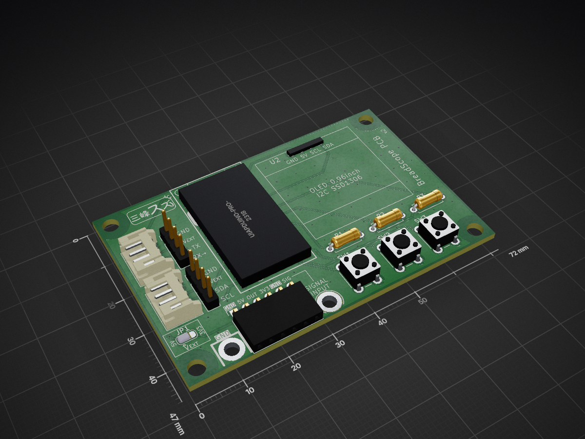
Hardware breadscope pcb is an open-source printed circuit board by verylowfreq, from the verylowfreq/breadscope repository on GitHub. It is a 2-layer board of 72 × 47 mm with 16 parts on 24 nets, routed with 126 tracks and 95 vias.
Its parts include 5 connectors, 3 resistors, 3 switches and 2 ICs. It belongs with the AVR (ATmega, ATtiny) boards of this library.
ブレッドボードで組める規模の簡易計測ツールのプラットフォーム。UIAPduino (CH32V003 / 32bit RISC-V) と共通基板をベースに、複数のファームウェアと、それらを操作・観測・ 書き換えするためのコンパニオンアプリ(Web / Android)をまとめたレポジトリです。
USB は rv003usb(ソフトウェア USB, low-speed HID)を全ファーム共通で使用し、ホスト側は USB-HID Feature Report でやり取りします。専用ドライバは不要(OS 標準 HID / WebHID)。
使い始めるには、まずはこちら。いちばん簡単な使い方(インストール不要の Web アプリ)から セルフテスト、ファームの書き換えまでを案内します。
添付の簡易説明書はこちら → BreadScopePCB_簡易説明書.pdf
| ディレクトリ | 内容 |
|---|---|
firmware_oscilloscope/ | 簡易オシロスコープのファーム(ch32fun + PlatformIO)。最初の製品 |
firmware_i2cscanner/ | I2C スキャナのファーム。ソフト I2C で外部バス(I2C_2)を走査し OLED 表示+USB-HID 操作 |
firmware_uartmonitor/ | UART モニターのファーム。RX 専用で受信し OLED に上書き表示。ボタンで速度切替+USB-HID 操作 |
firmware_servocontroller/ | サーボコントローラのファーム。SG90 系 PWM を PC3(TIM1_CH3) のハードウェア PWM で駆動。ボタン/OLED/USB-HID 操作 |
firmware_signalgen/ | 矩形波 周波数ジェネレータのファーム。PC3(TIM1_CH3) で 1Hz–1MHz・Duty 可変。ボタン/OLED/USB-HID 操作 |
vendor_rv003usb/ | rv003usb 本体(共有 git submodule, 全ファームで参照) |
app_web/ | WebHID コンパニオンアプリ(GitHub Pages で公開) |
app_android/ | Flutter 製 Android コンパニオンアプリ(USB-OTG) |
app_python/ | hidapi ベースの USB-HID デバッグ CLI |
hardware_breadscope_pcb/ | 共通基板の KiCad プロジェクト |
hardware_breadscope_pcb/ が UIAPduino (Pro Micro CH32V003 v1.4)
の各ピンに割り当てている信号(ネット)です。ピン名は UIAPduino のシルク表記
(Arduino Pro Micro 互換ラベル)です。
| 信号(ネット) | UIAPduino ピン | CH32V003 | 用途 |
|---|---|---|---|
SIG_INPUT | 1/A0 | PA2 | アナログ信号入力(ADC ch0) |
OUTPUT_1 | 5 | PC3 | 汎用出力(オシロ=1kHz 矩形波セルフテスト / サーボ=TIM1_CH3 ハードウェア PWM) |
I2C_1_SDA | 3(SDA) | PC1 | I2C バス1(オンボード OLED SSD1306) |
I2C_1_SCL | 4(SCL) | PC2 | 〃 |
I2C_2_SDA | 6/A2(SS) | PC4 | I2C バス2(外部引き出し。I2C スキャナが走査、要外部プルアップ) |
I2C_2_SCL | 0/A1 | PA1 | 〃 |
UART_1_TX | 15/A5(TX) | PD5 | UART 送信(UART モニターでは非駆動。USB プルアップ PD5 と共用) |
UART_1_RX | 16/A6(RX) | PD6 | UART 受信(UART モニターが使用) |
BUTTON_LEFT | 7(SCK) | PC5 | タクトスイッチ(左) |
BUTTON_CENTER | 9(MISO) | PC7 | タクトスイッチ(中) |
BUTTON_RIGHT | 8(MOSI) | PC6 | タクトスイッチ(右) |
| 電源 | 5V / 3V3 / GND | — | — |
SIG_INPUT・OUTPUT_1・I2C_1(OLED)・ボタン、I2C スキャナは I2C_1(OLED 表示)・
I2C_2(走査対象)、UART モニターは I2C_1(OLED 表示)・UART_1_RX(受信)・ボタン、
サーボは OUTPUT_1(PWM 出力)・I2C_1(OLED 表示)・ボタン)。PA2=A0, PC3=5, PC1=3(SDA), PC2=4(SCL),
PA1=A1, PC4=A2, PD5=A5, PD6=A6, PC5=7, PC6=8, PC7=9):
variant_CH32V003F4.hgit clone --recurse-submodules <this-repo>
# 既存クローンなら:
git submodule update --init --recursivecd firmware_oscilloscope && pio run(→ pio run -t upload で書き込み)。
I2C スキャナは cd firmware_i2cscanner、UART モニターは cd firmware_uartmonitor、
サーボは cd firmware_servocontroller で pio run。詳細は各 README
(firmware_oscilloscope/README.md /
firmware_i2cscanner/README.md /
firmware_uartmonitor/README.md /
firmware_servocontroller/README.md)。cd app_web && python -m http.server で Chrome/Edge から。公開は
GitHub Actions(.github/workflows/deploy-web.yml)が
app_web/ を Pages へデプロイ。詳細は app_web/README.md。cd app_android && flutter run。詳細は
app_android/README.md。python app_python/scope_usb.py status、
I2C スキャナは python app_python/i2cscan_usb.py list、
UART モニターは python app_python/uartmon_usb.py monitor など。両コンパニオンアプリは、接続デバイスの PID で機種(簡易オシロ / I2C スキャナ / UART モニター)を
自動判別し、1 つのアプリで対応します。また USB-HID ブートローダ(rv003usb, VID:PID 0x1209:0xB803)
経由でファームの書き込みにも対応します(minichlink 互換のスクラッチパッド実行方式)。
Suzu-M WorksBreadScope Oscilloscope /
I2C スキャナ BreadScope I2C Scanner / UART モニター BreadScope UART Monitor /
サーボ BreadScope Servo Controller)0x1209:0xD003 / I2C スキャナ 0x1209:0xD004 /
UART モニター 0x1209:0xD005 / サーボ 0x1209:0xD006 /
ブートローダ 0x1209:0xB803(全ファーム共通)MIT(LICENSE)。サードパーティ(rv003usb / webflasher 由来コード)の帰属は LICENSE と各ファイルのヘッダを参照。
| Qty | Value | Footprint | References |
|---|---|---|---|
| 3 | 4.7K | ProjectLibrary:R_Axial_DIN0207_L6.3mm_D2.5mm_P7.62mm_Horizontal | R1, R2, R3 |
| 3 | SW_Push | ProjectLibrary:SW_PUSH_6mm | SW1, SW2, SW3 |
| 2 | Conn_01x04_Pin | ProjectLibrary:PinHeader_1x04_P2.54mm_Vertical | J4, J5 |
| 2 | Conn_01x04_Socket | ProjectLibrary:JST_PH_S4B-PH-K_1x04_P2.00mm_Horizontal | J2, J3 |
| 2 | LOGO | ProjectLibrary:LOGO | G***, G*** |
| 1 | Conn_01x10_Socket | ProjectLibrary:PinSocket_1x06_P2.54mm_Horizontal | J1 |
| 1 | Jumper_3_Bridged12 | ProjectLibrary:SolderJumper-3_P1.3mm_Bridged12_RoundedPad1.0x1.5mm | JP1 |
| 1 | UIAPDUINO-PRO-MICRO-CH32V003-V1DOT4 | ProjectLibrary:UIAPDUINO-PRO-MICRO-CH32V003-V1DOT4 | U1 |
| 1 | ~ | ProjectLibrary:OLED_128x64_I2C_SSD1306 | U2 |
It measures 72 × 47 mm and has 2 copper layers, 1.6 mm thick.
16 parts. The full list of its parts is on this page, with links to each part's symbol and footprint where PCBKit's library has them.
From the verylowfreq/breadscope repository on GitHub, at the commit this page was made from: the board is hardware_breadscope_pcb/hardware_breadscope_pcb.kicad_pcb and its schematic hardware_breadscope_pcb/hardware_breadscope_pcb.kicad_sch. PCBKit opens the board in the browser, with nothing to install.
Its repository states no licence, so its author keeps all rights: ask verylowfreq before reusing the design.
google/mozc-devices
Circuit diagrams and firmware source code for Gboard DIY keyboards

conorpp/u2f-zero
U2F USB token optimized for physical security, affordability, and style

rusefi/rusefi
rusefi - GPL internal combustion engine control unit

VoronDesign/Voron-Hardware
Cool Hardware designed by the Voron Design group

hoglet67/RGBtoHDMI
Bare-metal Raspberry Pi project that provides pixel-perfect sampling of Retro Computer RGB/YUV video and conversion to HDMI

hackclub/OnBoard
💡 Join 1,000 teenagers and make your first PCB with a $100 grant!

