
2 layers70 × 34 mm
Connector breakout
veroxzik/pump-ac-conversion
A hyper-specific collection of mods for converting Pump It Up arcade pads to expensive USB controllers.
9 parts2GPL-3.0

 veroxzik/pump-ac-conversion2
A hyper-specific collection of mods for converting Pump It Up arcade pads to expensive USB controllers.
Pad board is an open-source printed circuit board by veroxzik, from the veroxzik/pump-ac-conversion repository on GitHub, published under the GPL-3.0 licence. It is a 2-layer board of 55 × 89.5 mm with 16 parts on 41 nets, routed with 133 tracks and 6 vias.
It is built around the 74AHCT1G125SE. Its parts include 8 connectors and 2 ICs. It belongs with the retro computing and games boards and the RP2040 boards of this library.
This repo contains files for my hyper-specific desire to get rid of all the rusted metal and busted sensors from my Pump It Up arcade pads.
It features the odd choice to keep bracketed panels, due to cost. In the future, I may modify the files to also support bracketless panels.
The code is designed around RP2040. Install the arduino-pico core and compiled using the Arduino IDE.
At the top of the code lists panelPins, an array grouping 4 pins for each of the 5 panels. You can change these if you are not using the boards as I've designed.
int panelPins[5][4] =
  {
    {0, 1, 2, 3},
    {4, 5, 6, 7},
    {8, 9, 10, 11},
    {12, 13, 14, 15},
    {16, 17, 18, 19}
  };
This code is simplistic. There's no debounce. If any switch is triggered, it will trigger the entire panel.
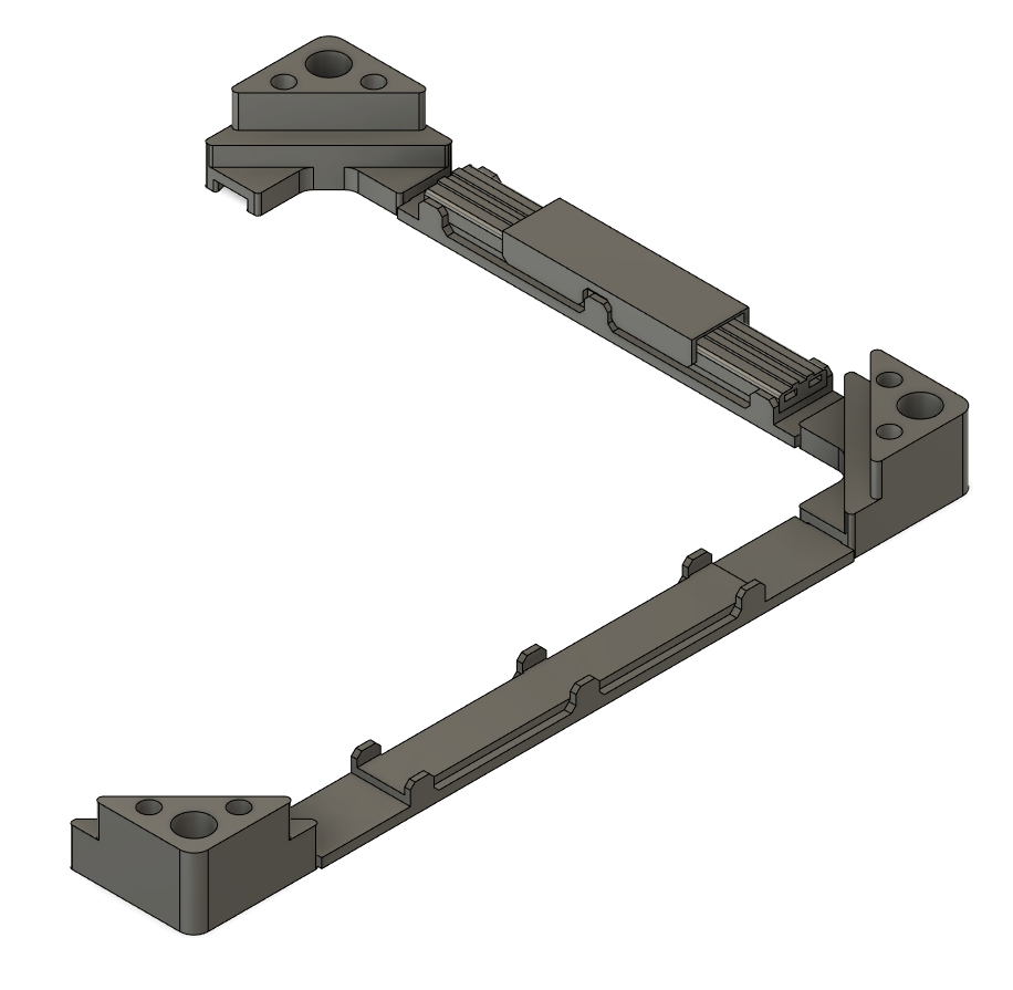
New frames were designed to be 3D printed (as all of mine were rusted). They are designed to use the existing bracketed panels and replaces the sensors with cheap generic dance sensors.
The frames are modular, consisting of corner supports and a choice of two side segments to form either the square or rectangle frames. A small printed top goes on the sensor to distribute the load and provide a place to tape mod.
A partial assembly is shown below:
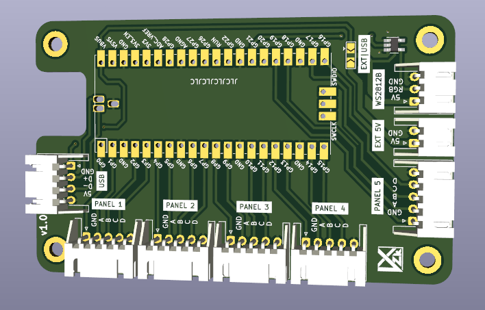
Two boards are contained in this repo.
The pad board takes a Raspberry Pi Pico as the main microcontroller, and has several JST XH connectors to mate with the connector boards, discussed below. There's also another JST XH connector for a WS2812B output, and for USB input.
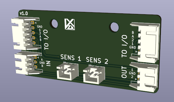
The connector boards are designed to screw into the area where the L-Bracket is mounted. Two are required for each panel. Each daughter board has (2) JST XH 2P connectors for the generic dance sensor, (2) JST XH 3P connectors for linking two connector boards together (OUT on one board goes to IN on the other), and (2) JST XH 5P connectors to bring signals back to the pad board (only one is necessary to use, but both are included for easier wire routing.
| Qty | Value | Footprint | References |
|---|---|---|---|
| 5 | XH-5 | Connector_JST:JST_XH_S5B-XH-A-1_1x05_P2.50mm_Horizontal | J1, J2, J3, J4, J5 |
| 4 | MountingHole | MountingHole:MountingHole_3.2mm_M3_DIN965_Pad | H1, H2, H3, H4 |
| 1 | 74AHCT1G125 | Package_TO_SOT_SMD:SOT-23-5_HandSoldering | U2 |
| 1 | Jumper_3_Open | Jumper:SolderJumper-3_P2.0mm_Open_TrianglePad1.0x1.5mm | JP1 |
| 1 | LOGO | VXZK:vxzk_logo | G*** |
| 1 | Pico | MCU_RaspberryPi_and_Boards:RPi_Pico_SMD_TH | U1 |
| 1 | XH-2 | Connector_JST:JST_XH_S2B-XH-A-1_1x02_P2.50mm_Horizontal | J8 |
| 1 | XH-3 | Connector_JST:JST_XH_S3B-XH-A-1_1x03_P2.50mm_Horizontal | J7 |
| 1 | XH-4 | Connector_JST:JST_XH_S4B-XH-A-1_1x04_P2.50mm_Horizontal | J6 |
veroxzik/pump-ac-conversion
A hyper-specific collection of mods for converting Pump It Up arcade pads to expensive USB controllers.


wntrblm/Big_Honking_Button
A simple Eurorack sampler and performance module in a silly package.

arturo182/keyboard_featherwing_hw
The Keyboard FeatherWing is an easy way to add a handheld Qwerty keyboard and a 2.6” color display (+ more) to your project! It fits well in your hands and is great for typing with your thumbs, early 2000s-style.

realworldpixel/home-assistant-keypad
A 9-key macro keypad for Home Assistant, running ESPHome. Every key is RGB backlit, and comes in two variants: one that sits on a desk and one that mounts on a wall, with magnets or screws.

romix123/P1-wifi-gateway
Deze software brengt verschillende componenten bij elkaar in een handzaam pakket.


It measures 55 × 89.5 mm and has 2 copper layers, 1.6 mm thick.
16 parts, built around the 74AHCT1G125SE. The full list of its parts is on this page, with links to each part's symbol and footprint where PCBKit's library has them.
From the veroxzik/pump-ac-conversion repository on GitHub, at the commit this page was made from: the board is boards/pad-board/pad-board.kicad_pcb and its schematic boards/connector-breakout/connector-breakout.kicad_sch. PCBKit opens the board in the browser, with nothing to install.
Its repository publishes it under the GPL-3.0 licence: you may reuse it on that licence's terms (keep the author's notice, and for a copyleft licence share your changes alike).