

4 layers241.2 × 327.2 mm

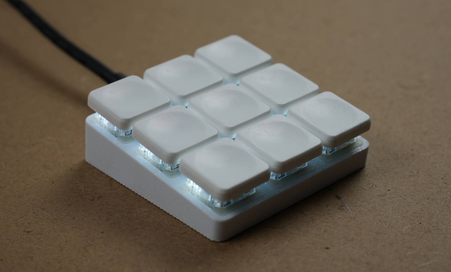
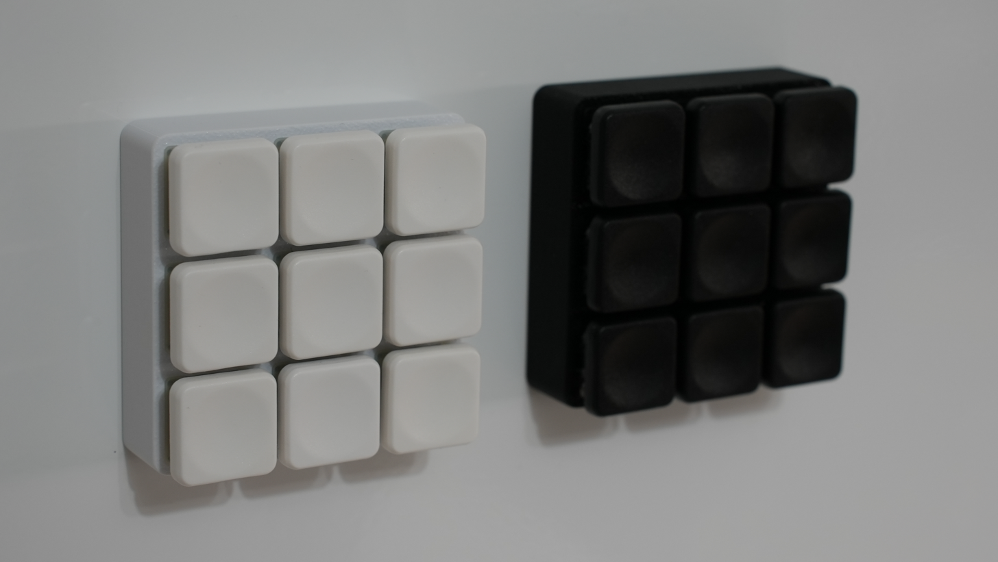
A 9-key macro keypad for Home Assistant, running ESPHome. Every key is RGB backlit, and comes in two variants: one that sits on a desk and one that mounts on a wall, with magnets or screws.
Keypad is an open-source printed circuit board by realworldpixel, from the realworldpixel/home-assistant-keypad repository on GitHub. It is a 2-layer board of 53 × 53 mm with 36 parts on 26 nets, routed with 172 tracks and 50 vias.
It is built around the 74AHCT1G125SE. Its parts include 10 capacitors, 9 diodes, 9 switches, 2 ICs and 1 resistor. It belongs with the keyboards and input boards and the ESP32 and RISC-V boards of this library.
A 9-key macro keypad for Home Assistant, running ESPHome. Every key is RGB backlit, and comes in two variants: one that sits on a desk and one that mounts on a wall, with magnets or screws.
Desk variant:
Wall variant:
Join the Discord if you want to follow along or ask questions: https://discord.gg/4yMsHbQQGn
Want a pre-assembled one instead of building it yourself? Join the waitlist: https://keypad.alex-labs.dev
Note: in the current revision of the board the level-shifter component is really small, and if you are not comfortable with SMD soldering already, you may have issues. Consider having the board populated by your vendor if you're not sure.
The part names link to a search, so you can pick whichever shop you prefer.
For the wall-mounted variant you also need:
The keycaps I used are these ones, variants
B-A1 V2 and W-A2 V2.
The XIAO usually ships with pin headers. You need two 7-pin strips, so keep them.
The board is 53 × 53 mm, 2 layers. Any fab house will work, but these instructions are for JLCPCB.
gerber.zip. Don't unzip it.| Option | Setting |
|---|---|
| Base Material | FR-4 |
| Layers | 2 |
| Dimensions | 53 × 53 (filled in automatically) |
| PCB Qty | 5 |
| Different Design | 1 |
| Delivery Format | Single PCB |
| PCB Thickness | 1.6 mm |
| Material Type | FR4 TG135 |
| Surface Finish | HASL (with lead) or Lead Free |
| Outer Copper Weight | 1 oz |
| Via Covering | Tented |
| Min via hole size | 0.3 mm / (0.4/0.45 mm) |
| Board Outline Tolerance | ±0.2 mm (Regular) |
| High-spec Options | leave as-is (all "No") |
Notes:
The STL files are in the enclosure folder. Pick desk or wall depending on the variant you
want. The wall variant also needs 4 magnet plugs.
I included an OrcaSlicer project with all the parameters already set:
enclosure/keypad-orca-slicer.3mf. It contains both variants, so disable the parts you don't need
before slicing.
The parts are designed to be printed in this orientation. Nothing needs supports.
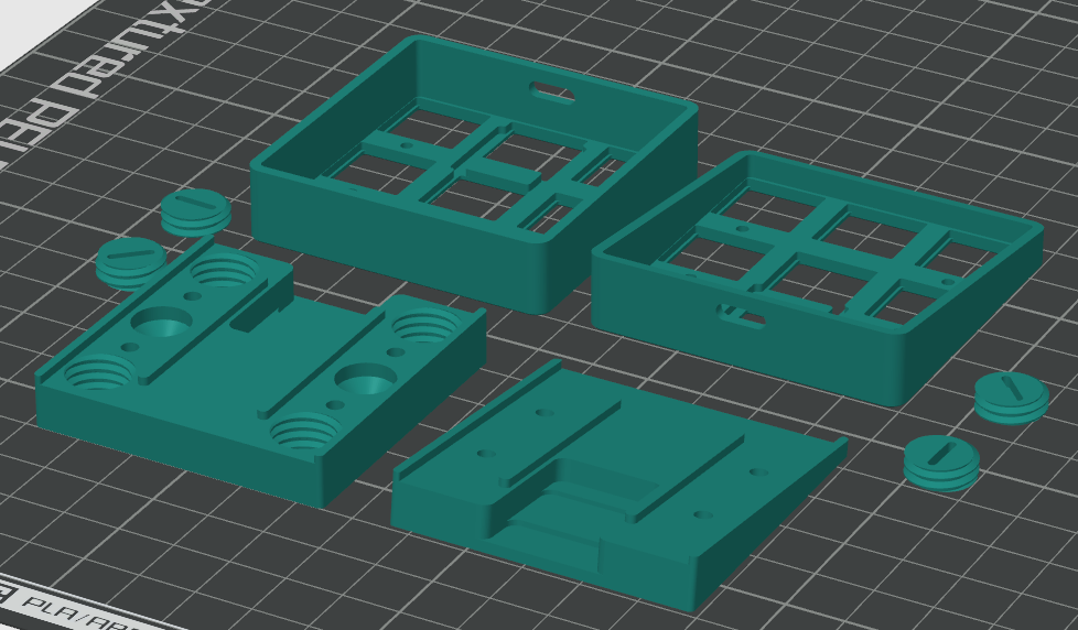
My settings:
| Printer | Bambu Lab P1S, 0.4 mm nozzle |
| Process | 0.16mm High Quality @BBL X1C |
| Filament | PLA |
| Build plate | Textured PEI |
If you slice the STL files yourself instead, these are the settings that matter:
| Setting | Value |
|---|---|
| Layer height | 0.16 mm (0.2 mm first layer) |
| Wall loops | 3 |
| Top / bottom shell layers | 6 / 4 |
| Sparse infill | 25%, rectilinear |
| Nozzle temperature | 220 °C |
| Bed temperature | 55 °C |
| Supports | off |
| Elephant foot compensation | 0.15 mm |
IMPORTANT: the top plates and the magnet plugs print at 100% infill, the bottom parts stay at 25%.
Tolerances are tight. If the board doesn't drop into the top shell, your parts have most likely shrunk. Scale them up a little, start with 100.5%, and reprint. In my case the original scale worked fine.
Do this in exactly this order.
There is a keyswitch "underneath" the ESP32 chip, so you must add the keyswitch before the ESP32.
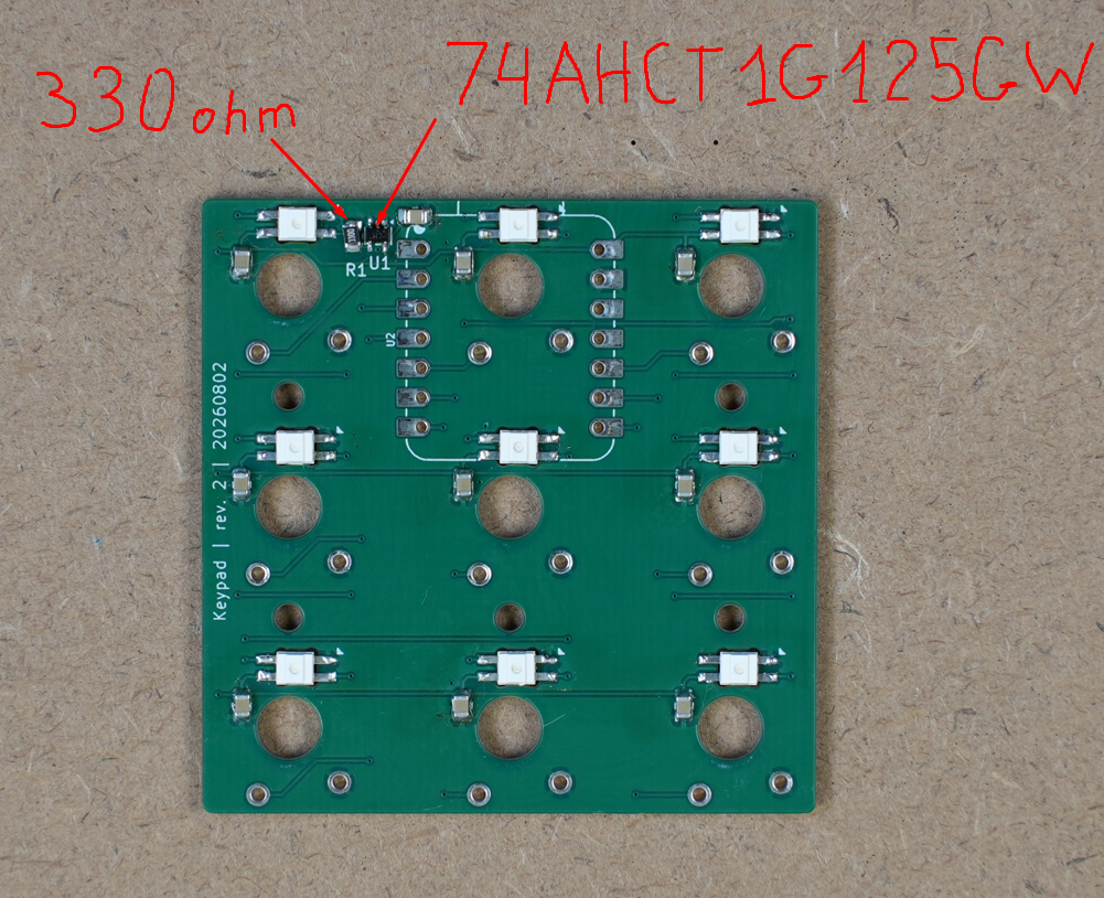
All the SMD parts go on the front side of the board, the switches go on the back later. The photos below show where each part sits.
R1 (330 Ω) and U1 (74AHCT1G125GW), both in the top left corner:
9 × SK6812MINI-E LED:
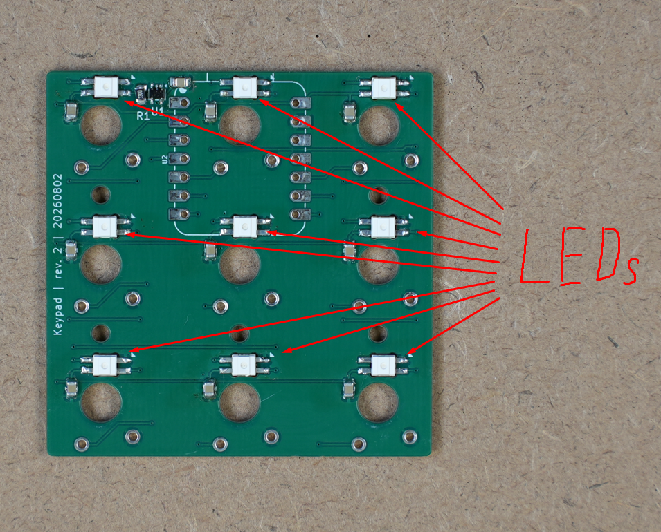
IMPORTANT: the LEDs go in one orientation only. The package has one corner cut at an angle, and the board has a small triangle printed next to every LED footprint. The cut corner points at the triangle. All 9 LEDs face the same way, so before you solder, check that all nine cut corners point in the same direction.
The LEDs are daisy chained, so a single LED turned the wrong way breaks the chain: that one and every LED after it stay dark.
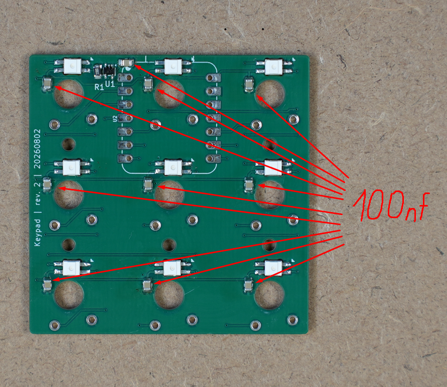
10 × 100 nF capacitor:
Put the two 7-pin headers into the U2 footprint from the front, pins pointing up, and solder them from the back.
To ensure the USB-C port lines up with the case, ensure the 10-pin headers are flush with the board.
It can be helpful to use the XIAO ESP32 that sits on these headers to align the pins while solderinb, but DO NOT SOLDER THE XIAO ESP32 TO THE HEADERS YET as we need to install the keyswitches.
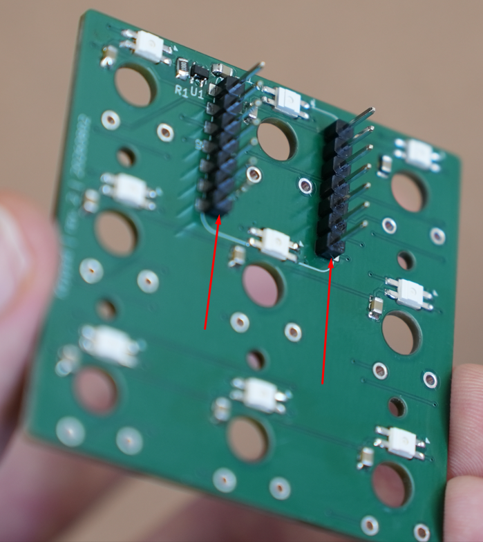
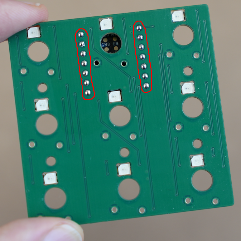
IMPORTANT: solder the headers to the PCB only. Don't solder the XIAO module onto them yet, it goes on in step 4.
If you're not comfortable in your soldering, now is a good time to test your board out.
Moving beyond this step and attaching the switches locks the board in place and it can be very hard to correct any mistakes after this point.
My XIAO ESP32 module appeared to connect to the pins on the header just being "inserted" into the headers and resting on them, and didn't require I finish soldering it to the headers and lock it in place, yours may or may not work similarly. You can test continuity between a pad and the pin it's supposed to connect to see if this works for you.
If this is the case for you, you can set the module on the headers, and temporarily skip ahead to the steps on how to configure it in esphome and try it manually using the web interface to verify the LEDs work. If you can toggle on the LEDs and they work, this proves almost all the components
If you're stuck - examine the level shifter pins to make sure they are lining up with the pads, it is by far the toughest component. If things still aren't working, you can use the continuity mode of a multimeter and make sure all GND pins on the LEDs are connected to each other, as well as 5V. You can check this out by viewing the PCB layout in KiCad (or KiCanvas can work if you don't use KiCad) and looking for pins labelled GND or VBUS/+5V.
IMPORTANT: install all the switches in the top shell first, then put the PCB in the shell and solder them in place.
Press all 9 switches into the top shell from the inside until they click:
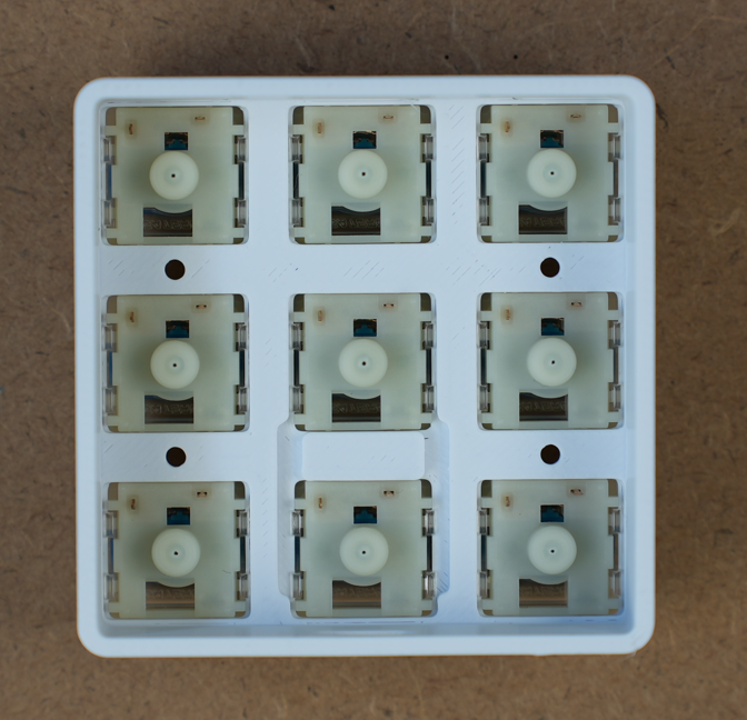
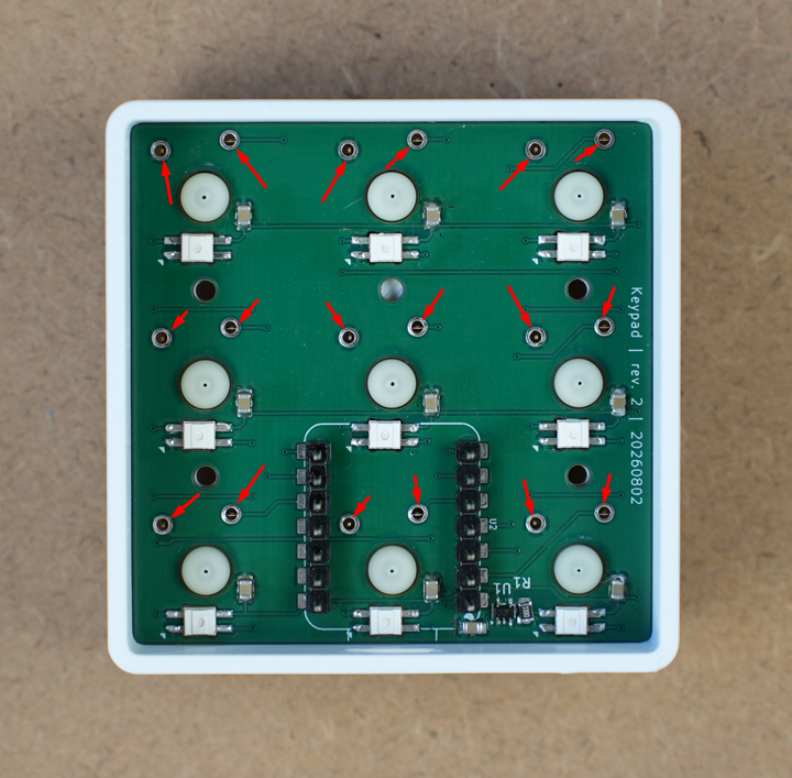
Then drop the PCB onto the switch pins, SMD side up. Each switch has two pins that come through the board, so solder all 18:
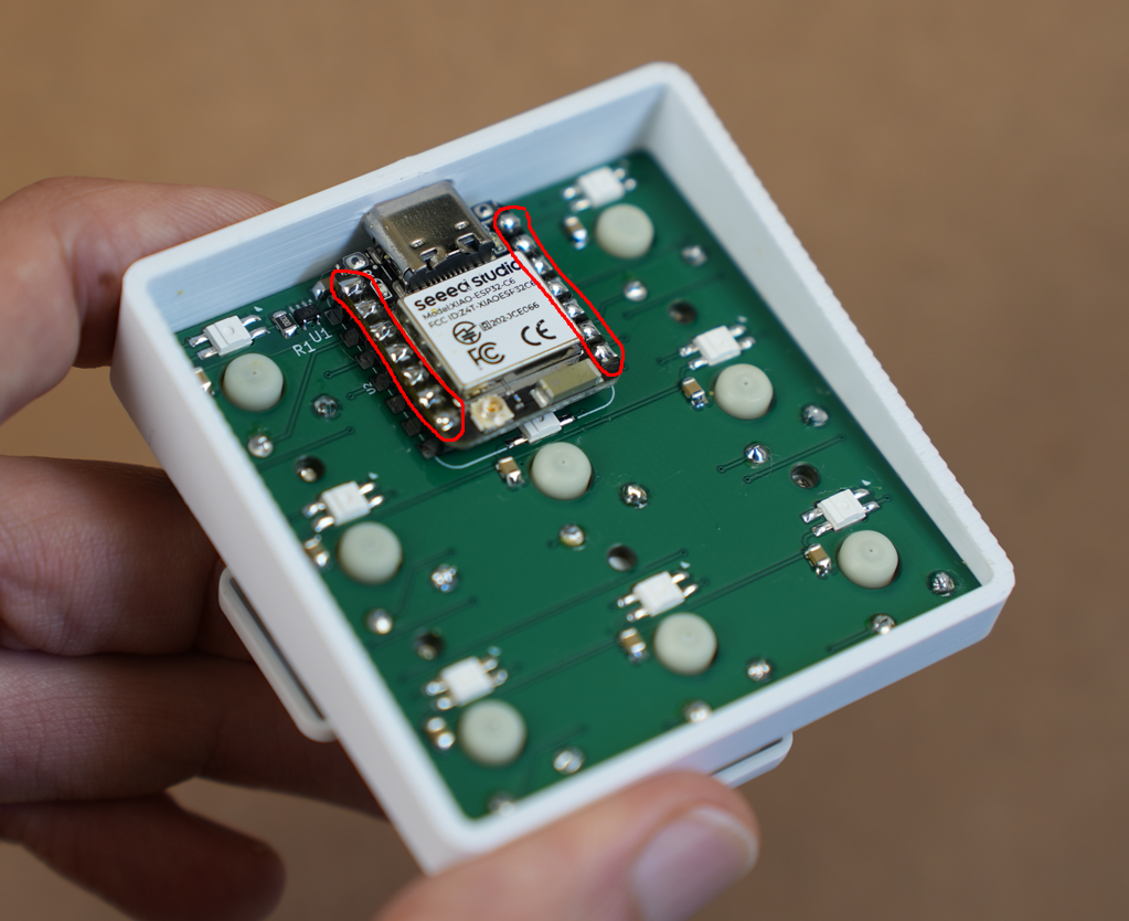
Push the XIAO onto the two headers, with the USB-C connector pointing at the slot in the shell wall, and solder both rows, 14 joints. Trim the header pins with the flush cutters.
The desk variant is the simplest one. Press the heat-set inserts into the four holes. A soldering iron with a conical tip works well for this.
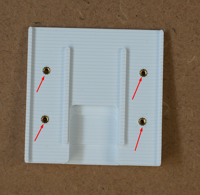
Then screw the top and bottom parts together with the 4 screws. They go in from the front, between the switches.
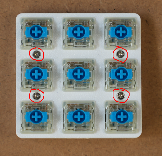
Install the keycaps and it's done!
The wall variant uses the same inserts and the same 4 screws to hold the two parts together. On top of that it has 4 beds for the magnets and 4 printed caps that hold the magnets in place.
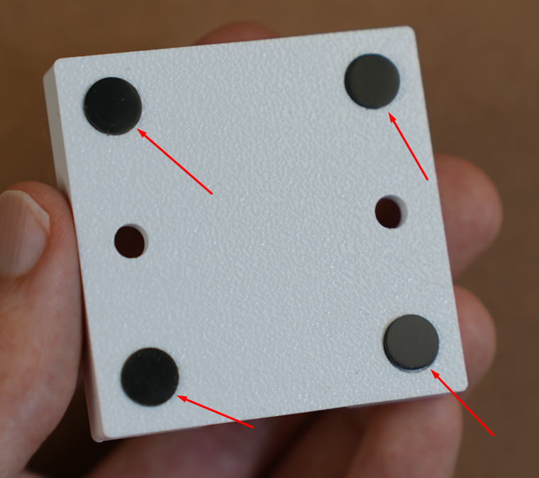
The beds are the corner holes. The 2 smaller holes in the middle are for the wall screws.
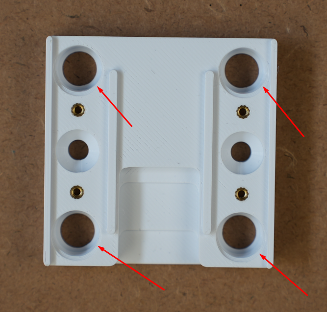
Put the magnets in place and screw the caps in. The caps have a slot, so a flat screwdriver works.
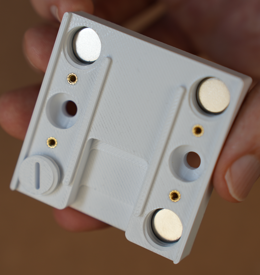
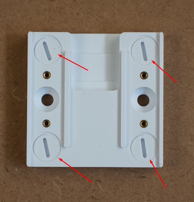
Finally, add the silicone rubber pads on the other side. Punch them out of the silicone sheet with the 8 mm gasket punch.
ESPHome is a tool that turns a YAML file into firmware for ESP32 boards, no coding needed.
esphome.yaml in this repo is not a whole config, it is only the part that describes the 9 keys and
the 9 LEDs. You paste it under the config ESPHome writes for you.
keypad and pick Seeed Studio XIAO ESP32C6. It asks for your
wifi once and remembers it.esphome.yaml there. Change nothing above it: the generated API key, OTA and wifi blocks are
yours, and the file doesn't touch them. See below for what you should end up with.This is what the wizard writes in step 2. Your name, key and hotspot password will be different. Leave all of it alone and paste at the bottom:
esphome:
  name: keypad
  friendly_name: keypad

esp32:
  variant: esp32c6
  flash_size: 4MB
  framework:
    type: esp-idf

logger:

api:
  encryption:
    key: "the key generated for you, don't share it"

ota:
  - platform: esphome

wifi:
  ssid: !secret wifi_ssid
  password: !secret wifi_password
  ap:
ssid: keypad Fallback HotspotYou get 18 entities:
| Entity | What it does |
|---|---|
| Key 1 … Key 9 | fires press or long_press |
| LED 1 … LED 9 | RGB light, one per key |
In an automation, trigger on a key entity and branch on its event_type attribute. The hold time is
1 second; change long_press_ms at the top of the config to adjust it.
CC BY-NC-SA 4.0. Build it, modify it, share it, but not commercially, and credit the original. See LICENSE for the details and for the third-party footprint libraries used in the KiCad project.
| Qty | Value | Footprint | References |
|---|---|---|---|
| 10 | C | Capacitor_SMD:C_0805_2012Metric | C1, C2, C3, C4, C5, C6, C7, C8, C9, C10 |
| 9 | KS33_SK6812MINI-E | PCM_marbastlib-gateron_lp:LED_KS33_6028R | LED1, LED2, LED3, LED4, LED5, LED6, LED7, LED8, LED9 |
| 9 | KS33_SW_solder | PCM_marbastlib-gateron_lp:SW_KS33_1u | SW1, SW2, SW3, SW4, SW5, SW6, SW7, SW8, SW9 |
| 1 | 220 | Resistor_SMD:R_0805_2012Metric | R1 |
| 1 | 74AHCT1G125 | Package_TO_SOT_SMD:SOT-353_SC-70-5 | U1 |
| 1 | XIAO-ESP32-C6-DIP | Seeed_Studio_XIAO_Series:XIAO-ESP32-C6-DIP | U2 |
The 31 most common of 36 parts.


wntrblm/Big_Honking_Button
A simple Eurorack sampler and performance module in a silly package.

arturo182/keyboard_featherwing_hw
The Keyboard FeatherWing is an easy way to add a handheld Qwerty keyboard and a 2.6” color display (+ more) to your project! It fits well in your hands and is great for typing with your thumbs, early 2000s-style.

romix123/P1-wifi-gateway
Deze software brengt verschillende componenten bij elkaar in een handzaam pakket.


calvin-mcd/universal-vault
pcb for the vault35 covering all sorts of layout options
It measures 53 × 53 mm and has 2 copper layers, 1.6 mm thick.
36 parts, built around the 74AHCT1G125SE. The full list of its parts is on this page, with links to each part's symbol and footprint where PCBKit's library has them.
From the realworldpixel/home-assistant-keypad repository on GitHub, at the commit this page was made from: the board is pcb/keypad.kicad_pcb and its schematic pcb/keypad.kicad_sch. PCBKit opens the board in the browser, with nothing to install.
Its repository states no licence, so its author keeps all rights: ask realworldpixel before reusing the design.