4 layers241.8 × 174.8 mm

 ve2cuy/breadboard-PC
Ordinateur 8088/8086 sur breadboard (VE2CUY): firmware/BIOS, moniteur, BASIC, pont Arduino/STM32, schemas KiCad, images PC-DOS de reference.
Breadboard PC is an open-source printed circuit board by ve2cuy, from the ve2cuy/breadboard-PC repository on GitHub. It is a 2-layer board of 100 × 100 mm with 27 parts on 115 nets, routed with 725 tracks and 18 vias.
It is built around the 74LS373SC, 74HC245D and 74LS00SC. Its parts include 9 ICs, 8 resistors, 4 connectors, 2 switches and 1 diode. It belongs with the STM32 boards of this library.


A microcomputer with a PC/XT-inspired architecture, built on solderless breadboards around an Intel 8088. Its ROM, whose source code is written entirely in 8086 assembly language, boots into an interactive menu, runs two BASIC interpreters and boots PC-DOS 2.1 and MS-DOS 3.30 from floppy disk images.
A project by Alain Boudreault (VE2CUY), 2026. Version française
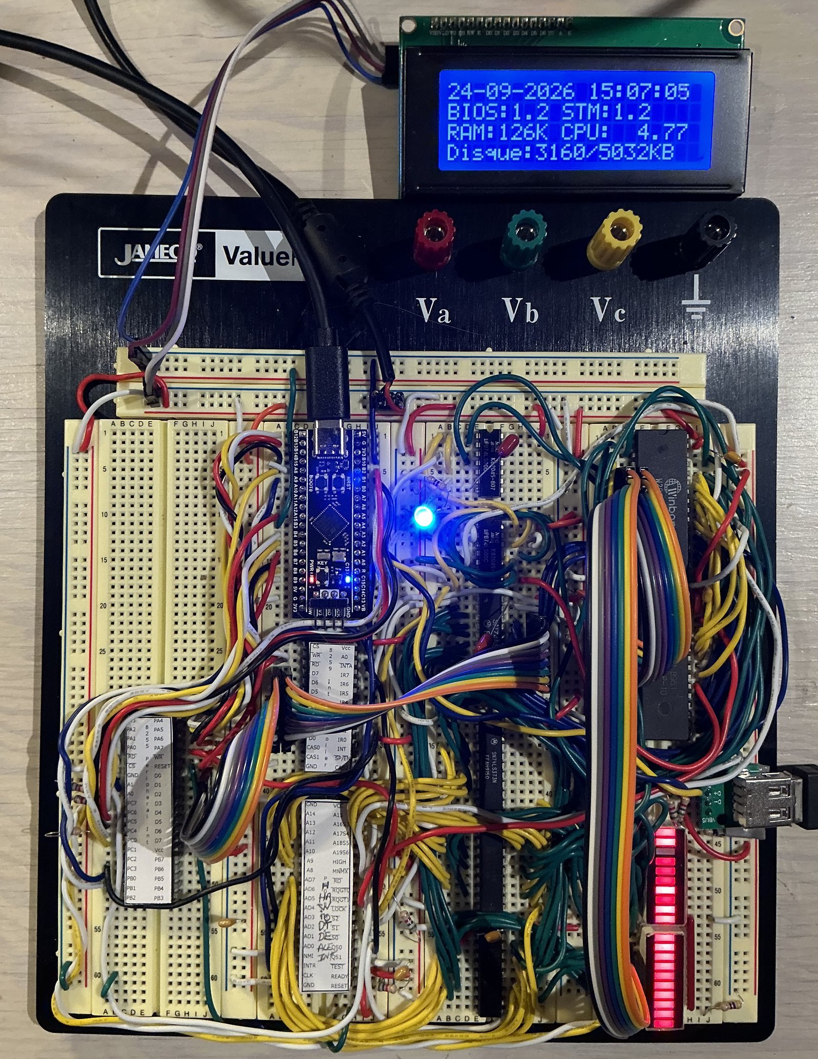
The build: the Black Pill STM32F411 bridge (top centre), the 8088, the 8255, the 8259, the ROM and
the RAM. The LCD shows the “Information” screen (date and time, versions, RAM, disk, speed).
| Processor | Intel 8088, 4.77 MHz by default (adjustable from 1 to 10 MHz) |
| Memory | 256 KB ROM (W29C020C, C0000h–FFFFFh), 128 KB static RAM (HM628128, 00000h–1FFFFh) |
| I/O | 8255A in mode 2 (bus to the bridge), 8259A (interrupts), 4×20 I2C LCD, PS/2 keyboard |
| Bridge | WeAct Black Pill STM32F411 board: keyboard, USB terminal, LCD, clock, disk, RESET |
| Software | ROM written entirely in assembly (NASM, strict 8086 instruction set), both BASICs included: menu, BIOS for DOS, Tiny BASIC, GW-BASIC-style BASIC |
| Operating systems | PC-DOS 2.1 and MS-DOS 3.30, booted from a floppy disk image |
The core of the machine (processor, address latches, ROM, RAM, decoding) is wired on breadboards with 74HC/74HCT logic and no programmable logic (no GAL, no CPLD). Address decoding takes only a few NAND gates:
A19 = 1 (window C0000h–FFFFFh);A19 = 0;80h–83h): A7 and an I/O cycle;20h–21h): NAND(IO, A5) (one gate of a 74LS00).
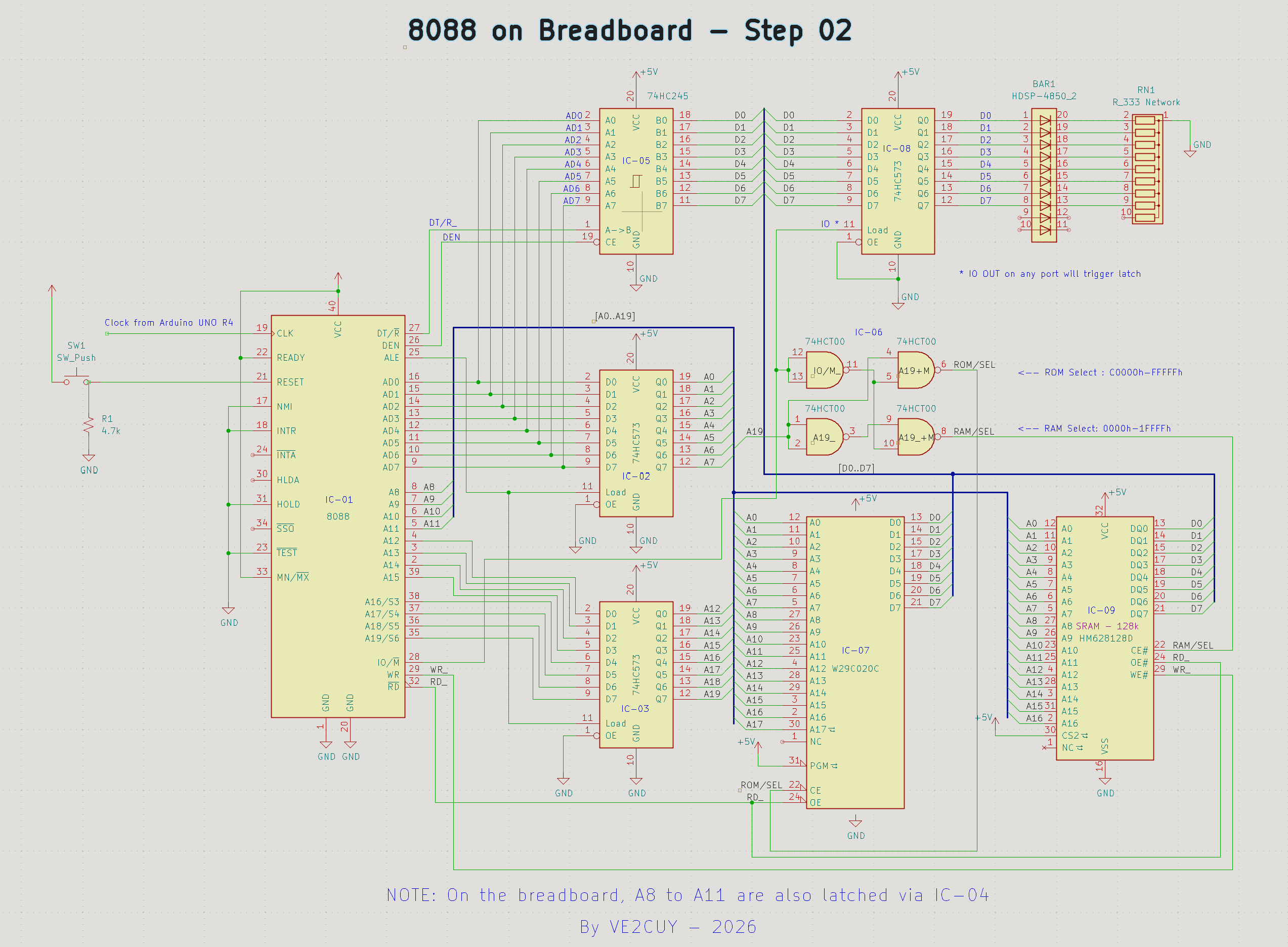
Schematic of the core (KiCad). The clock, supplied here by an Arduino UNO R4, now comes from the bridge.
The 8088 does not bit-bang any peripheral. All traffic goes through a single 8255 in mode 2: an
8-bit bidirectional bus with hardware handshaking, connected to the bridge. Every byte received from
the bridge raises an interrupt (IR1 of the 8259).
flowchart LR
    CPU["Intel 8088"] --- BUS(("Bus<br>A0-A19 / D0-D7"))
    BUS --- ROM["256 KB ROM<br>W29C020C"]
    BUS --- RAM["128 KB RAM<br>HM628128"]
    BUS --- PIO["8255A<br>mode 2"]
    BUS --- PIC["8259A"]
    PIO -- "INTR → IR1" --> PIC
    PIC -- INTR --> CPU
    PIO <== "Port A (8 bits) + handshake" ==> BRIDGE["Bridge<br>Black Pill STM32F411"]
    BRIDGE -- "CLK, RESET" --> CPU
    KBD["PS/2 keyboard"] --> BRIDGE
    BRIDGE <-- "USB (serial + drive)" --> PC["PC: terminal"]
    BRIDGE --> LCD["4×20 I2C LCD"]
    BRIDGE --- FLASH["8 MB flash<br>FAT16"]
The bridge wiring in detail (pins, 3.3 V / 5 V levels, pull-up resistors) is described (in French) in arduino/8088_bridge_stm32/README.md.
The bridge firmware (a PlatformIO project, arduino/8088_bridge_stm32) gives the 8088 the peripherals of a PC:
| Function | Details |
|---|---|
| PS/2 keyboard | Frame decoding; raw scan codes passed to the 8088 |
| Terminal | Native USB serial port to the PC (ANSI, 80 columns) |
| Display | 4×20 HD44780 LCD over I2C (PCF8574) |
| Real-time clock | STM32 RTC (32.768 kHz crystal): TIME$, DATE$, INT 1Ah |
| Disk | 8 MB W25Q64 SPI flash formatted FAT16: files, sectors, floppy images mounted as A: |
| USB drive | The flash is exposed to the PC as a USB drive (USB ON / USB OFF) to copy files onto it |
| 8088 clock | CLK signal generated by hardware PWM, 1 to 10 MHz |
| 8088 RESET | Held while the bridge starts up; Ctrl-Alt-Del (PS/2) or Ctrl-\ (terminal) |
The 8088 talks to the bridge through a command protocol on a dedicated channel (see Solution-01/lib/bridge.asm).
At power-up, the ROM displays a menu on both the terminal and the LCD. It can be driven from either the PS/2 keyboard or the terminal; Esc returns to the main menu.
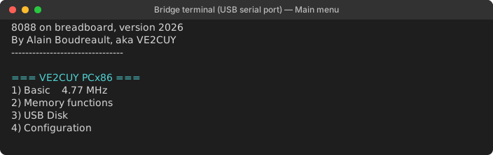
| Menu | Options |
|---|---|
| 1) Basic | Tiny BASIC; GW-BASIC-style BASIC |
| 2) Memory functions | Memory dump and editing, CPU registers, code entry and execution, interrupt vector table, RAM test |
| 3) USB Disk | USB drive toggle, file list, booting a disk image |
| 4) Configuration | Clock speed, CPU speed test, date and time setting, information screen |
An original reimplementation inspired by GW-BASIC: same keywords, same error messages, integers, single-precision floating point (in software) and strings. About 54 KB are free for programs.
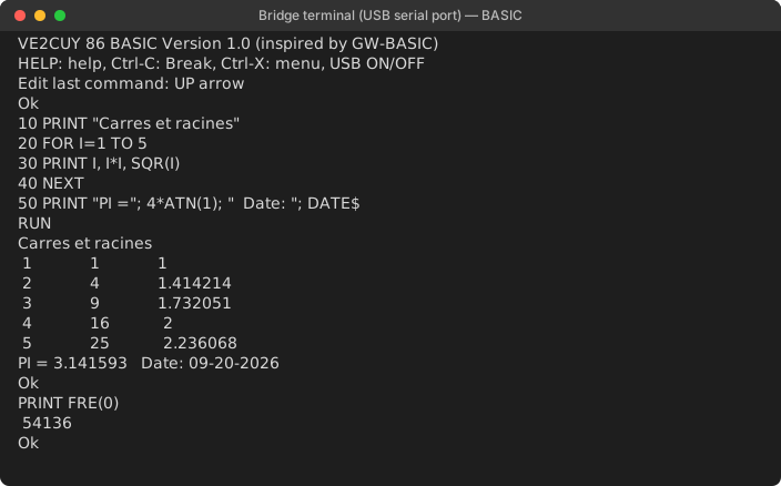
| Category | Commands and functions |
|---|---|
| Program | RUN LIST EDIT DELETE NEW CLEAR CONT TRON TROFF HELP SYSTEM |
| Control flow | IF…THEN…ELSE GOTO GOSUB/RETURN ON…GOTO/GOSUB FOR…NEXT WHILE…WEND END STOP |
| Data | LET DIM ERASE SWAP DATA/READ/RESTORE DEF FN DEFINT/DEFSNG/DEFSTR |
| Input/output | PRINT INPUT LINE INPUT INKEY$ CLS LOCATE COLOR BEEP |
| Math | ABS SGN INT FIX SQR SIN COS TAN ATN LOG EXP RND RANDOMIZE |
| Strings | LEN LEFT$ RIGHT$ MID$ INSTR CHR$ ASC STR$ VAL HEX$ UCASE$ STRING$ |
| Files | SAVE LOAD MERGE FILES KILL FORMAT; OPEN PRINT # INPUT # EOF CLOSE |
| Clock | TIMER TIME$ DATE$ (read and set the bridge RTC) |
| Machine | PEEK POKE DEF SEG INP OUT WAIT CALL FRE |
| Disk and system | DSKREAD DSKWRITE USB ON/OFF BOOT "image.img" |
The ROM provides the BIOS layer a DOS expects: disk (INT 13h, CHS and LBA), keyboard (INT 16h),
clock (INT 1Ah), text output to the terminal (INT 10h) and bootstrap (INT 19h). A floppy image
copied to the flash (through the USB drive) is mounted as drive A: and booted from
USB Disk → 3) Boot disk image, or with BOOT "PCDOS2_1.IMG" from BASIC. DOS writes go to the
image file.
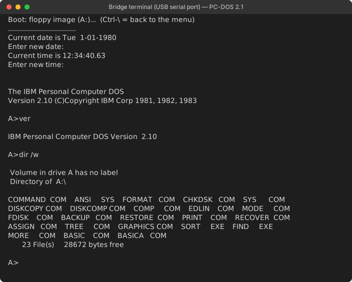
PC-DOS 2.1: booting from the image (one dot per sector read), VER, DIR /W
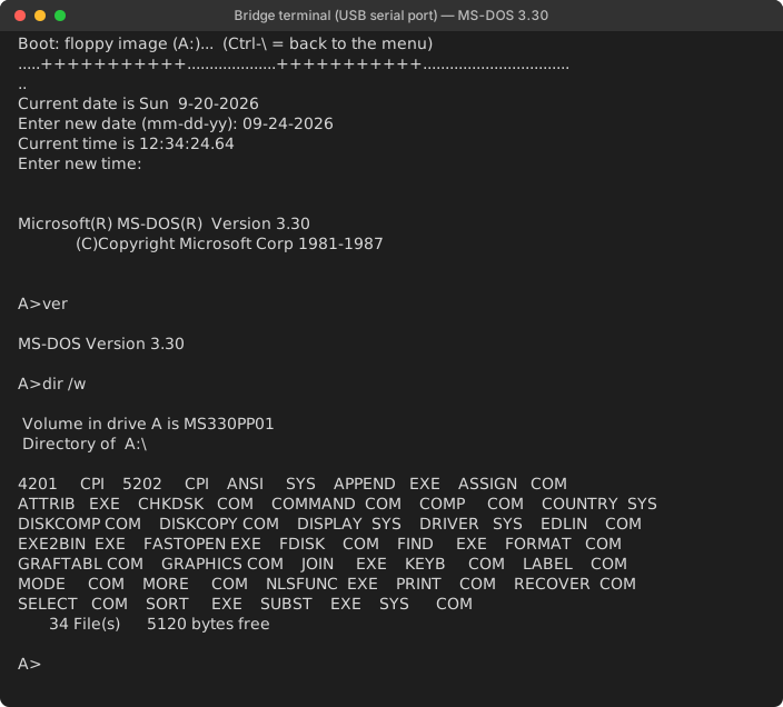
MS-DOS 3.30
Limitations: 128 KB of RAM (DOS 5.0 and later require 256 KB), no video hardware (programs that write to video memory display nothing), DOS keyboard input from the terminal only.
cd Solution-01
make            # solution-01.bin (256 KB, to be burned into the W29C020C); make rom-en for English
make check      # checks size, reset vector and signature
make test       # test benches under emulation (Unicorn)
make test-rom   # full ROM simulation: DOS, BASIC, PS/2 keyboard
Tools: NASM, GNU Make, Python 3 (+ unicorn for the tests); PlatformIO for the bridge
(platformio run -e blackpill_f411ce_usbdrive -t upload, board in DFU mode).
| Folder | Contents |
|---|---|
| Solution-01/ | 8088 ROM (NASM) and tests; full technical documentation (in French) in Solution-01/README.md |
| arduino/8088_bridge_stm32/ | Firmware of the Black Pill STM32F411 bridge (PlatformIO) |
| kicad/ | Schematics of the build |
| PC-DOS/ | Test floppy disk images |
| medias/ | Datasheets, schematics and screenshots |
The terminal screenshots on this page are produced by the actual (English) ROM, running in the project's simulator (medias/captures/generer.py).
| Qty | Value | Footprint | References |
|---|---|---|---|
| 4 | 10k | Resistor_THT:R_Axial_DIN0207_L6.3mm_D2.5mm_P7.62mm_Horizontal | R2, R3, R4, R7 |
| 3 | 4.7k | Resistor_THT:R_Axial_DIN0207_L6.3mm_D2.5mm_P7.62mm_Horizontal | R1, R5, R6 |
| 2 | 74LS00 | Package_DIP:DIP-14_W7.62mm | IC-6, U9 |
| 2 | 74LS373 | Package_DIP:DIP-20_W7.62mm | U2, U3 |
| 1 | 1-2: STM32 2-3: ext. | Connector_PinHeader_2.54mm:PinHeader_1x03_P2.54mm_Vertical | JP1 |
| 1 | 1k | Resistor_THT:R_Axial_DIN0207_L6.3mm_D2.5mm_P7.62mm_Horizontal | R8 |
| 1 | 5V 2A | Connector_BarrelJack:BarrelJack_Horizontal | J3 |
| 1 | 74HC245 | Package_DIP:DIP-20_W7.62mm | U6 |
| 1 | 8088 | Package_DIP:DIP-40_W15.24mm | U1 |
| 1 | 8255A | Package_DIP:DIP-40_W15.24mm | U11 |
| 1 | 8259A | Package_DIP:DIP-28_W15.24mm | U7 |
| 1 | CLK externe | Connector_PinHeader_2.54mm:PinHeader_1x02_P2.54mm_Vertical | J4 |
| 1 | HM628128D | Package_DIP:DIP-32_W15.24mm | U8 |
| 1 | IR0 test | Button_Switch_THT:SW_PUSH_6mm | SW2 |
| 1 | LCD I2C | Connector_PinHeader_2.54mm:PinHeader_1x04_P2.54mm_Vertical | J2 |
| 1 | PWR | LED_THT:LED_D3.0mm | D1 |
| 1 | RESET | Button_Switch_THT:SW_PUSH_6mm | SW1 |
| 1 | STM32F411 BlackPill | Black-Pill:STM32F411_Black_Pill | U5 |
| 1 | USB_A (clavier PS/2) | Connector_USB:USB_A_Molex_67643_Horizontal | J1 |
| 1 | W29C020C | Socket:DIP_Socket-32_W11.9mm_W12.7mm_W15.24mm_W17.78mm_W18.5mm_3M_232-1285-00-0602J | U4 |
It measures 100 × 100 mm and has 2 copper layers, 1.6 mm thick.
27 parts, built around the 74LS373SC, 74HC245D and 74LS00SC. The full list of its parts is on this page, with links to each part's symbol and footprint where PCBKit's library has them.
From the ve2cuy/breadboard-PC repository on GitHub, at the commit this page was made from: the board is kicad/Breadboard-pc/Breadboard-pc.kicad_pcb and its schematic kicad/Breadboard-pc/Breadboard-pc.kicad_sch. PCBKit opens the board in the browser, with nothing to install.
Its repository states no licence, so its author keeps all rights: ask ve2cuy before reusing the design.

Nakazoto/CenturionComputer
This is just a simple backup of all the files related to the Centurion that I have stored on my HD. The Wiki itself has far more in-depth information about the Centurion and it's individual cards.


tebl/C64-CPM-Cartridge
A recreation of the CP/M cartridge for the Commodore 64.


ceteras/Cobra-XP
Derived from Cobra, an experimental board for testing all kind of mods.