4 layers60 × 28 mm

 UtkarshVerma/mu-probe3
My personal take on the Black Magic Debug v2.1.
Mu probe is an open-source printed circuit board by UtkarshVerma, from the UtkarshVerma/mu-probe repository on GitHub. It is a 2-layer board of 18 × 36 mm with 62 parts on 68 nets, routed with 703 tracks and 88 vias.
It is built around the 74LVC2T45DC, SPX3819M5-L-3-3 and USBLC6-2SC6. Its parts include 22 resistors, 21 capacitors, 7 ICs, 4 diodes and 4 connectors. It belongs with the sensors and measurement and interfaces and adapters boards and the STM32 boards of this library.


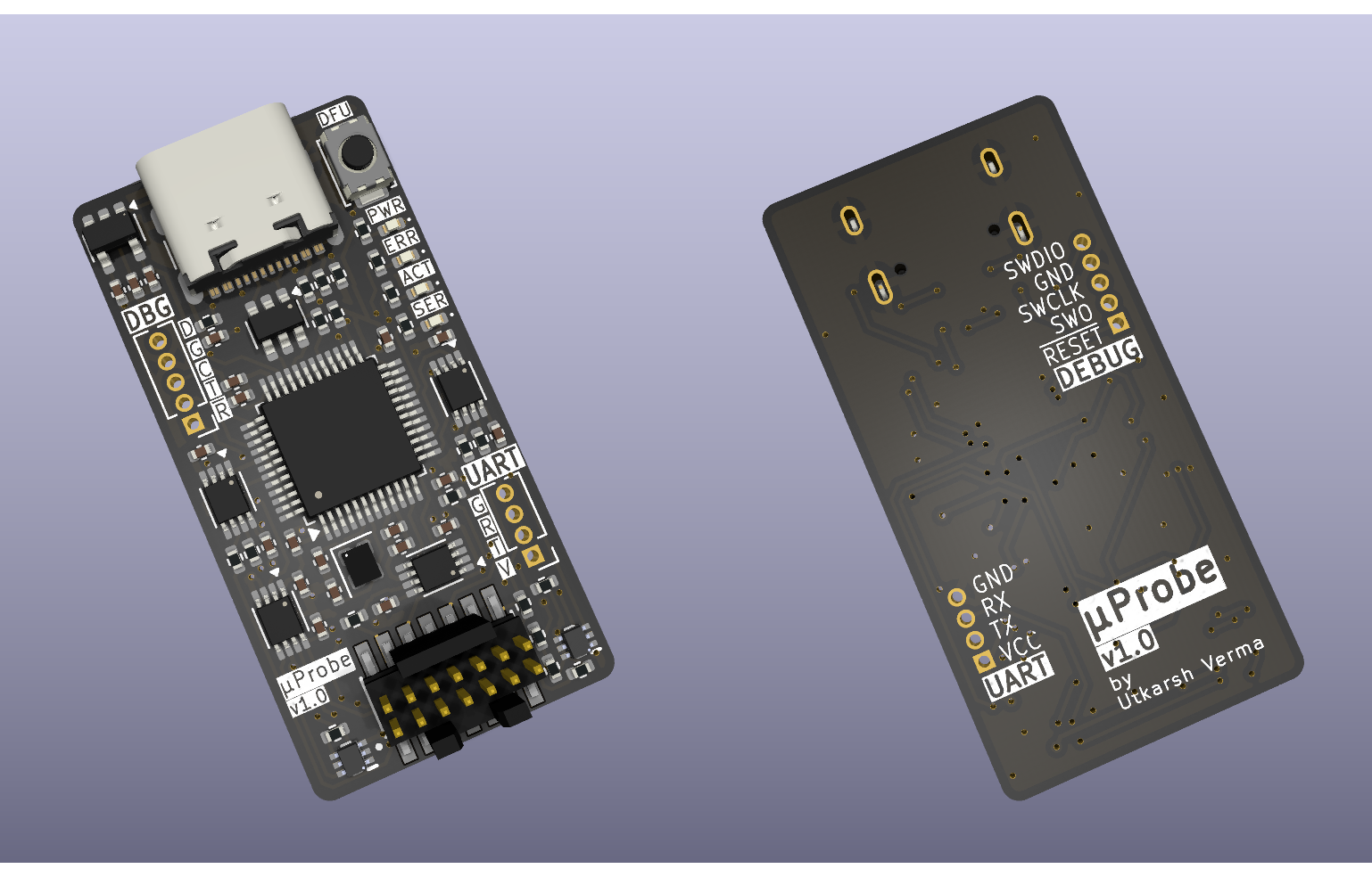
This probe is my personal take on the Black Magic Debug project's Black Magic Probe v2.1. I was disappointed to find out that I could not use my STLink v3 on non-ST targets1, even when they used the same protocol. One thing led to another and I stumbled upon the Black Magic Probe. The idea of having a configurable debugger appealed to me. This combined with an itch to work on a hardware project is what brought μProbe into existence.
[!note] Please buy the official Black Magic Probe if you can! It is necessary to support the awesome work that the folks at the Black Magic project do.
This project would not have been possible without the following resources:
Lastly, I would also like to thank the warm community at 1BitSquared's Discord server for their insights and help.
| Qty | Value | Footprint | References |
|---|---|---|---|
| 14 | 100n | Capacitor_SMD:C_0402_1005Metric | C1, C2, C6, C7, C8, C9, C10, C11, C12, C13, C16, C17, C18, C19 |
| 8 | 100 | Resistor_SMD:R_0402_1005Metric | R12, R13, R14, R15, R16, R17, R18, R19 |
| 5 | 10k | Resistor_SMD:R_0402_1005Metric | R2, R3, R6, R7, R21 |
| 4 | 330 | Resistor_SMD:R_0402_1005Metric | R8, R9, R10, R11 |
| 4 | 74LVC2T45DC | Package_SO:VSSOP-8_2.3x2mm_P0.5mm | U3, U4, U5, U6 |
| 3 | 4.7u | Capacitor_SMD:C_0402_1005Metric | C3, C5, C15 |
| 2 | 12p | Capacitor_SMD:C_0402_1005Metric | C20, C21 |
| 2 | 4.7k | Resistor_SMD:R_0402_1005Metric | R1, R20 |
| 2 | 5.1k | Resistor_SMD:R_0402_1005Metric | R4, R5 |
| 1 | 1.5k | Resistor_SMD:R_0402_1005Metric | R22 |
| 1 | 10n | Capacitor_SMD:C_0402_1005Metric | C4 |
| 1 | 1u | Capacitor_SMD:C_0402_1005Metric | C14 |
| 1 | 8 MHz | footprints:Crystal_4P_GND24 | Y1 |
| 1 | Conn_ST_STDC14 | footprints:SAMTEC_FTSH-107-01-L-DV-K | J2 |
| 1 | DEBUG | Connector_PinHeader_1.27mm:PinHeader_1x05_P1.27mm_Vertical | J3 |
| 1 | DFU | Button_Switch_SMD:SW_Push_SPST_NO_Alps_SKRK | SW1 |
| 1 | DMG1023UV-7 | footprints:SOTFL50P162X60-6N | Q1 |
| 1 | DMG1024UV-7 | footprints:SOTFL50P162X60-6N | Q2 |
| 1 | GREEN | LED_SMD:LED_0402_1005Metric | D1 |
| 1 | ORANGE | LED_SMD:LED_0402_1005Metric | D2 |
| 1 | RED | LED_SMD:LED_0402_1005Metric | D3 |
| 1 | SPX3819M5-L-3-3 | Package_TO_SOT_SMD:SOT-23-5 | U2 |
| 1 | STM32F103CBTx | Package_QFP:LQFP-48_7x7mm_P0.5mm | U7 |
| 1 | UART | Connector_PinHeader_1.27mm:PinHeader_1x04_P1.27mm_Vertical | J4 |
| 1 | USBLC6-2SC6 | Package_TO_SOT_SMD:SOT-23-6 | U1 |
| 1 | USB_C_Receptacle_USB2.0_16P | Connector_USB:USB_C_Receptacle_GCT_USB4105-xx-A_16P_TopMnt_Horizontal | J1 |
| 1 | YELLOW | LED_SMD:LED_0402_1005Metric | D4 |

Misaka0x2730/MioLink
ARM JTAG/SWD debugger (BlackMagic port) based on RP2040.

casartar/Black-Smoke-Probe
Ich habe den letzten öffentlich zugänglichen Schaltplan genommen und die Micro-USB durch eine USB-C Buchse ersetzt.


TUDSSL/DIPS
This is the official public repository for DIPS: Debugger for Intermittently-Powered Systems. The repository consists of all components that make DIPS: - Hardware - Debugger Firmware - Emulator Firmware - Emulator Host…


bassammorsy/stm32-flight-controller
Custom 4-layer STM32F405RGTx quadcopter flight controller PCB designed in KiCad. Betaflight compatible, 4S–6S LiPo input, SMT assembled by JLCPCB.
It measures 18 × 36 mm and has 2 copper layers, 1.6 mm thick.
62 parts, built around the 74LVC2T45DC, SPX3819M5-L-3-3 and USBLC6-2SC6. The full list of its parts is on this page, with links to each part's symbol and footprint where PCBKit's library has them.
From the UtkarshVerma/mu-probe repository on GitHub, at the commit this page was made from: the board is main.kicad_pcb and its schematic main.kicad_sch. PCBKit opens the board in the browser, with nothing to install.
Its repository states no licence, so its author keeps all rights: ask UtkarshVerma before reusing the design.