2 layers44.5 × 31.7 mm

 Uspizig/WifiWallSwitch4
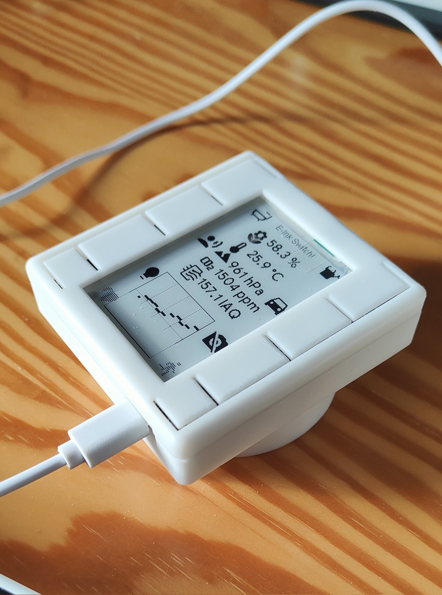
A WallSwitch with a clever EINK Display that measures your Air Quality, measures Temperature, detects movement, measures Light Conditions... and many more.
S3-27-epaper touch is an open-source printed circuit board by Uspizig, from the Uspizig/WifiWallSwitch repository on GitHub. It is a 2-layer board of 65.4 × 68 mm with 159 parts on 140 nets, routed with 1,814 tracks and 156 vias.
It is built around the ESP32-S3-WROOM-1-N8, BME280 and BME680, with the SIQ-02FVS3, MMC5883MA and RFM95W-868S2 among its other parts. Its parts include 40 resistors, 26 capacitors, 17 ICs, 14 diodes and 13 connectors. It belongs with the lEDs and displays boards and the ESP32 boards of this library.


A WallSwitch with a clever EINK Display that measures your Air Quality, measures Temperature, detects movement, measures Light Conditions... and many more. And the Best of all: "It can be your own LOCAL Voice Assistant or MediaPlayer"
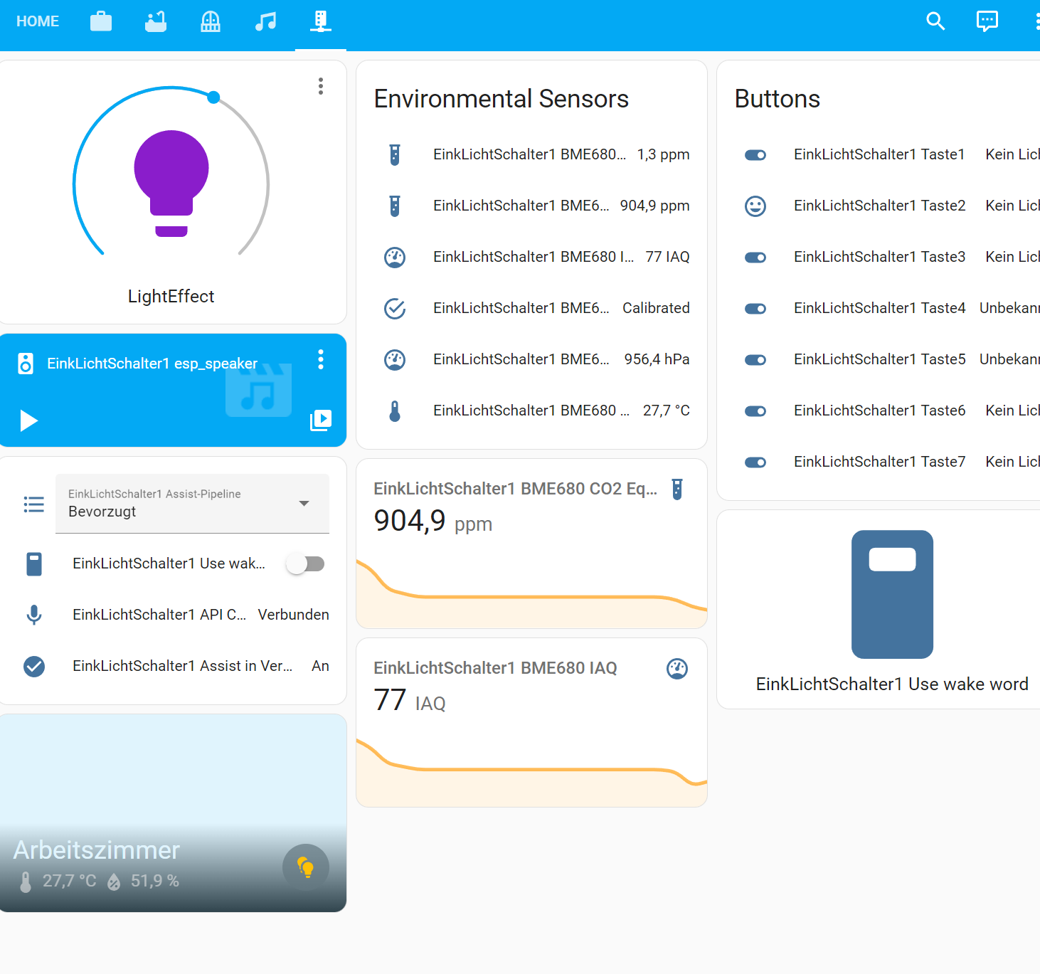
This Device perfectly integrates in your Smart Home (e.g. HomeAssistant or IO Broker).
No permanent backlight On Display that disturbs your sleep. Just a brillant E-Ink Display with outstanding contrast and some Buttons that you can feel when you swipe over with your plam.
A lightweight Design with a perfect WAF Factor. Fits on your Desktop or on your wall.
The device can be programmed, adapted, hacked, tinkered and individualised by YOU.
You want to push boundries even further: Use Arduino and do a deep Dive in Ultra Low Power Mode. The Battery might run for Years with an intelligent Power Gateing.
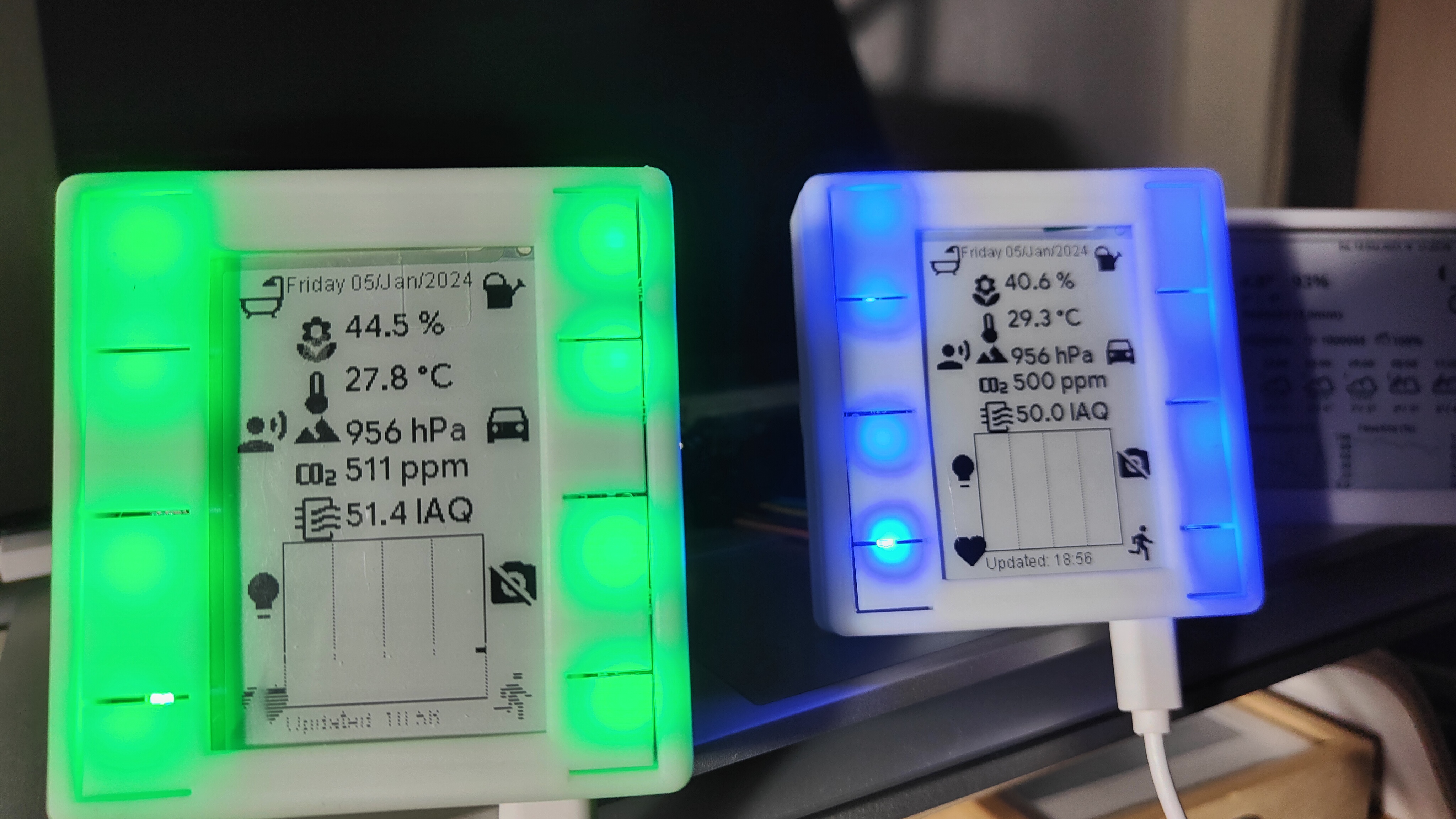
Eight Ambient Light LEDs can give you a visual quick feedback if needed:
View of the components in HomeAssistant
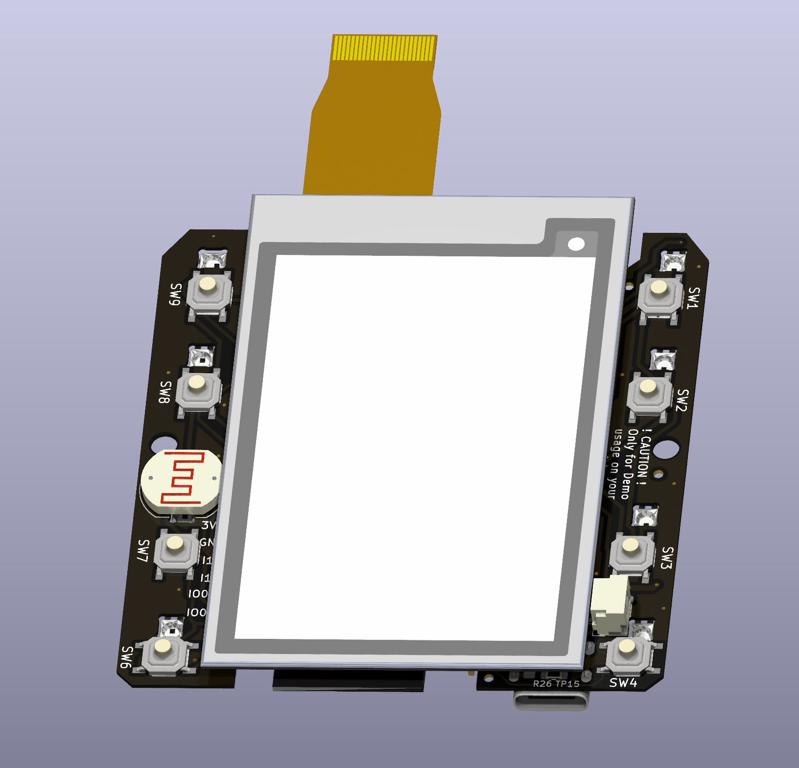
What is under the hood:
Main thing you see when you have a first look is the massive 2.7 " E-Ink Screen
See it in Action here: https://twitter.com/USpizig/status/1747731234338336940
Hardware Specs:
Underneath the EINK Screen is a placeholder for an optional RFM95/RFM98 Long Range Communication Module. This Module works with LoRa, FSK or other wireless standards. Up 15km Range of communication can be established with this module. Perfect as well for decoding your Bresser Weather Station and translate it to MQTT for your Smart Home.
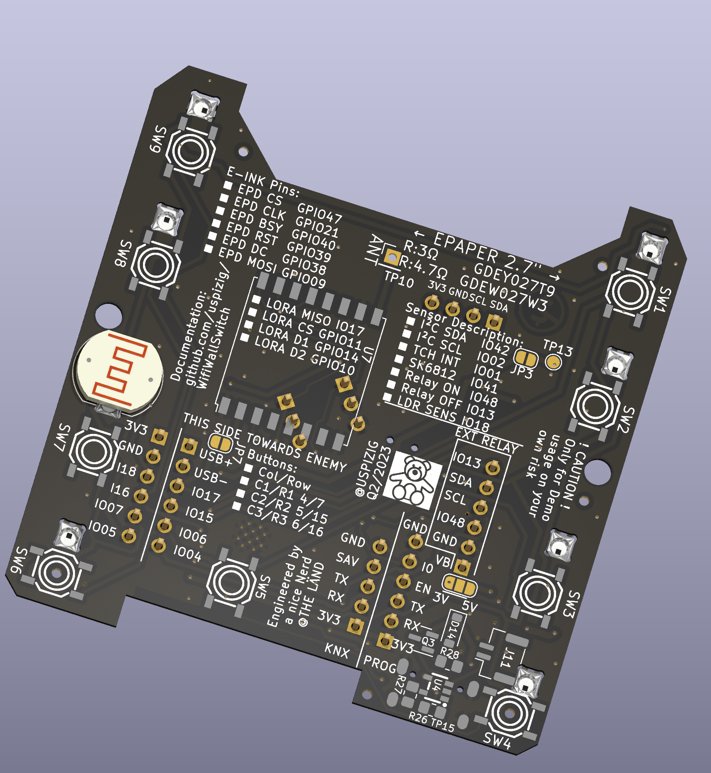
The other side of the PCB looks like this:
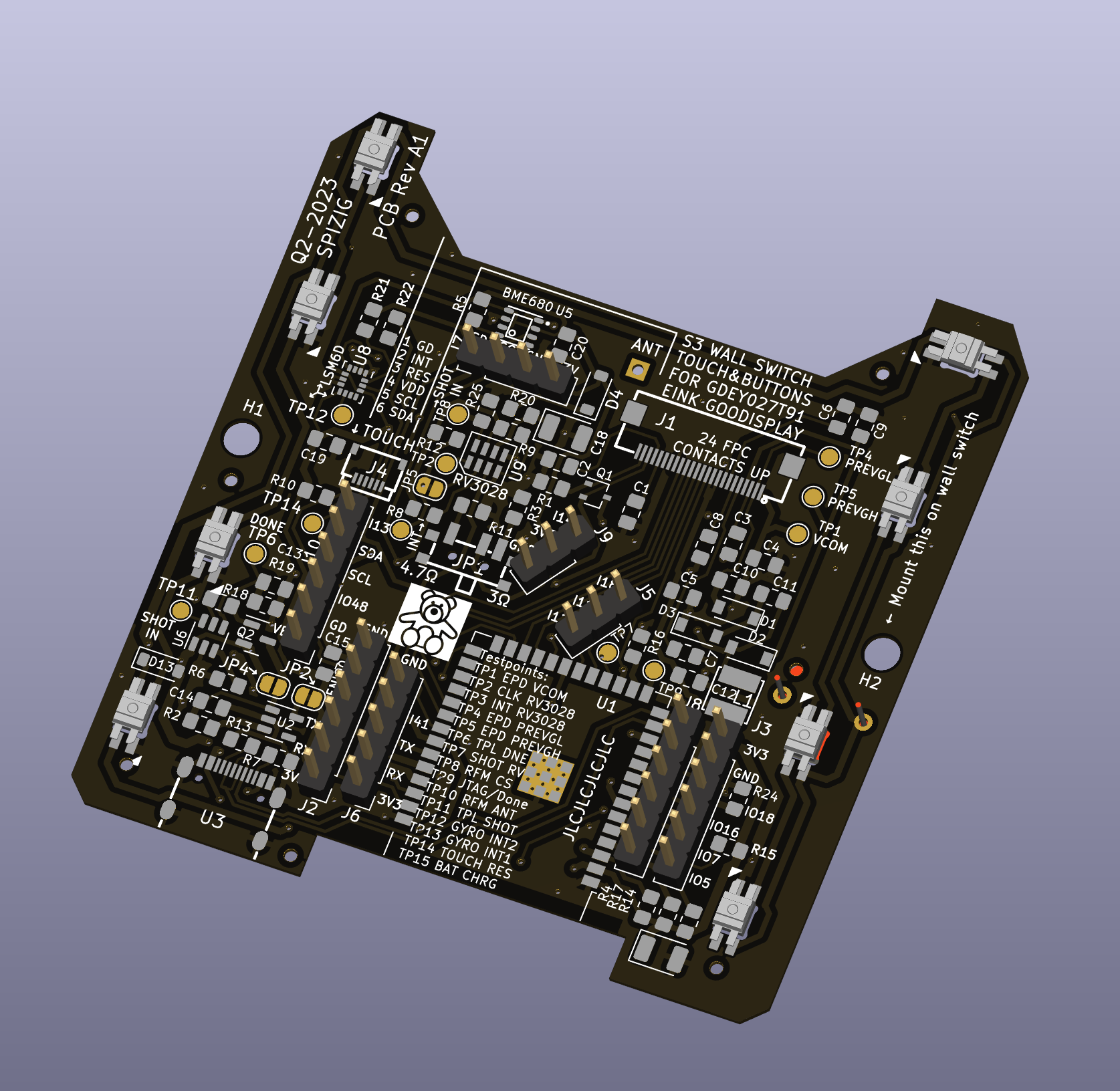
If you scroll further down you may see a picture of the TOP View of the PCB On the Top side of the PCB you see the Main Processor: This is an ESP32-S3 and various sensors:
And another view with all the SMD Parts simulated:
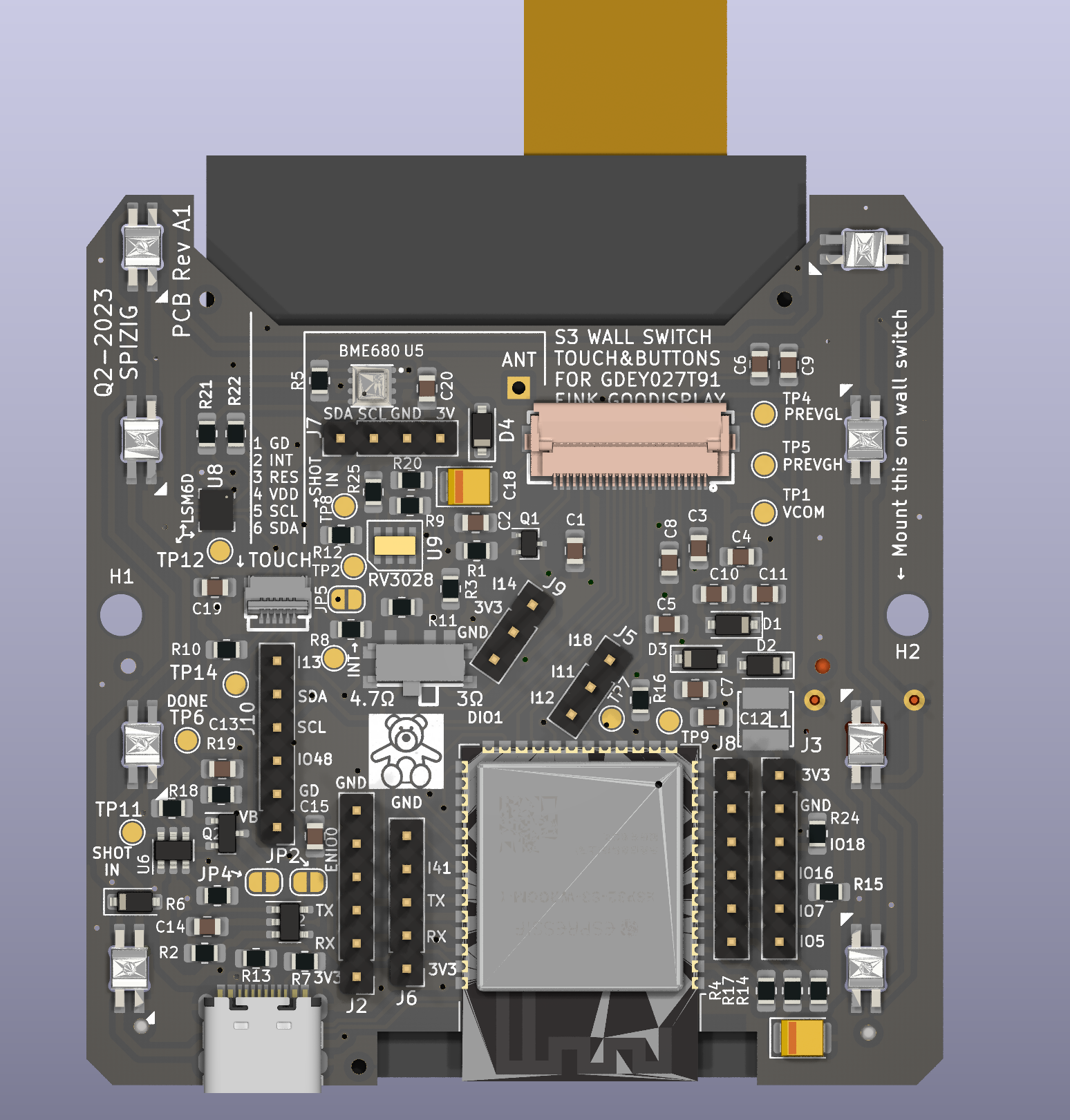
What is currently working:
Hardware:
The optional Modules are still under test
Software Sketches working: Arduino:
Home Assistant with ESPHome Integration:
Known ESPHome Issues right now:
Known Issues on Arduino:
What is planned:
WARNINGS This is my hobby. Please do NOT be a DIRTY COPY CAT and make your own comercial product out of it. See License before you copy anything out of it.
If you use this Hardware, Software, Code or schematics you agree that any harm, damage, burn or injuries are YOUR RESPONSIBILITY! The Author may not be held liable for any damage that might happen if you try this code out or use this product or parts of it. Legal validity of this disclaimer: This disclaimer is to be regarded as part of the internet publication which you were referred from. If sections or individual terms of this statement are not legal or correct, the content or validity of the other parts remain uninfluenced by this fact.
Referrals and links The author is not responsible for any contents linked or referred to from his pages - unless he has full knowledge of illegal contents and would be able to prevent the visitors of his site from viewing those pages. If any damage occurs by the use of information presented there, the author might not be liable. Furthermore the author is not liable for any postings or messages published by users of discussion boards, guest books or mailing lists provided.
Arduino: Before you compile please ensure you modify all your credentials and used sensors in "credentials.h" which have been marked REPLACEMEUSER This Source Code is provided "AS it is" . Also ensure you have installed the following libs: Code Sources that influenced this Source Code and which libaries you may need:
https://github.com/knolleary/pubsubclient/blob/master/examples/mqtt_auth/mqtt_auth.ino https://randomnerdtutorials.com/esp32-mqtt-publish-subscribe-arduino-ide/ RGBW for SK6812: Original code by Jim Bumgardner (http://krazydad.com). Modified by David Madison (http://partsnotincluded.com). Extended by Christoph Wempe https://gist.github.com/CWempe?direction=desc&sort=created
Adafruit BME/BMP280/SGP30 sketches/libs Please consider buying their products due to their great work in Arduino libs https://github.com/adafruit/Adafruit_SGP30 https://github.com/adafruit/Adafruit_BMP280_Library
Bosch BME680 BSEC Lib https://github.com/BoschSensortec/BSEC-Arduino-library
Andreas Spiess OTA Sketch for OTA Update of the ESP32 over Wifi https://github.com/SensorsIot/ESP32-OTA
Knolleary pubsubclient /pubsubclient/blob/master/examples/mqtt_auth/mqtt_auth https://github.com/knolleary/pubsubclient
Fastled https://github.com/FastLED/FastLED
Settings for Jumpers & Solder Bridges: Jumper:
I²C Address of onboard Devices.
Testpoints for soldering and Tinkering: TP1 EPD VCOM -> Debuging of EINK TP2 CLK RV3028 TP3 INT RV3028 TP4 EPD PREVGL -> Debuging of EINK TP5 EPD PREVGH -> Debuging of EINK TP6 TPL DNE -> Debuging of EINK... Connect to a GPIO for Ulatra Low Power sleep and fire a 1 whenever you want to Deep Sleep on that GPIO TP7 SHOT RV3028 -> Wakeup Pin for RTC2 TP8 RFM CS -> Soldering Pin needed for RFM95 TP9 JTAG/Done TP10 RFM ANT -> Connector for 868 MHZ Antenna TP11 TPL SHOT -> Wakeup Pin for TPL 5110 RTC TP12 GYRO INT2 TP13 GYRO INT1 TP14 TOUCH RES -> Touch Controller Reset Pin. Hopefully never needed TP15 BAT CHRG -> Battery charg Pin. Hopefully never needed.
Known HW Limitations:
TODO:
| Qty | Value | Footprint | References |
|---|---|---|---|
| 15 | 10K | Resistor_SMD:R_0805_2012Metric_Pad1.20x1.40mm_HandSolder | R1, R2, R4, R5, R8, R9, R10, R12, R14, R15, R17, R18, R19, R25, R28 |
| 12 | 1uF | Capacitor_SMD:C_0805_2012Metric_Pad1.18x1.45mm_HandSolder | C1, C2, C3, C4, C5, C6, C7, C8, C14, C15, C16, C17 |
| 9 | SW_Push | tp4056:SW-SMD_4P-CORR-L5.2-W5.2-P3.70-LS6.4 | SW1, SW2, SW3, SW4, SW5, SW6, SW7, SW8, SW9 |
| 8 | SK6812MINI-E | tp4056:MX_SK6812MINI-E | D5, D6, D7, D8, D9, D10, D11, D12 |
| 6 | 100nF | Capacitor_SMD:C_0805_2012Metric_Pad1.18x1.45mm_HandSolder | C13, C19, C20, C21, C22, C26 |
| 6 | 10k | Resistor_SMD:R_0603_1608Metric_Pad0.98x0.95mm_HandSolder | R34, R35, R36, R37, R38, R39 |
| 6 | MBR0530 | Diode_SMD:D_SOD-123 | D1, D2, D3, D4, D13, D14 |
| 4 | 4.7uF 50V_US | Capacitor_SMD:C_0805_2012Metric_Pad1.18x1.45mm_HandSolder | C9, C10, C11, C12 |
| 4 | Jumper_2_Bridged | Jumper:SolderJumper-2_P1.3mm_Bridged_RoundedPad1.0x1.5mm | JP2, JP3, JP5, JP11 |
| 4 | Jumper_2_Open | Jumper:SolderJumper-2_P1.3mm_Open_RoundedPad1.0x1.5mm | JP4, JP8, JP12, JP14 |
| 4 | N.C. | Resistor_SMD:R_0603_1608Metric_Pad0.98x0.95mm_HandSolder | R16, R24, R29, R30 |
| 4 | VCOM | TestPoint:TestPoint_Pad_D1.5mm | TP1, TP7, TP9, TP13 |
| 3 | 5k11 | Resistor_SMD:R_0805_2012Metric_Pad1.20x1.40mm_HandSolder | R7, R13, R27 |
| 3 | Conn_01x06 | Connector_PinHeader_2.54mm:PinHeader_1x06_P2.54mm_Vertical | J2, J3, J8 |
| 2 | 0.47R | Resistor_SMD:R_0805_2012Metric_Pad1.20x1.40mm_HandSolder | R11, R40 |
| 2 | 0R | Resistor_SMD:R_0805_2012Metric_Pad1.20x1.40mm_HandSolder | R21, R22 |
| 2 | BME280 | Package_LGA:Bosch_LGA-8_2.5x2.5mm_P0.65mm_ClockwisePinNumbering | U13, U16 |
| 2 | Conn_01x03_Pin | Connector_PinHeader_2.54mm:PinHeader_1x03_P2.54mm_Vertical | J5, J9 |
| 2 | Jumper_2_Bridged | Jumper:SolderJumper-2_P1.3mm_Open_RoundedPad1.0x1.5mm | JP9, JP13 |
| 2 | Jumper_3_Bridged12 | Jumper:SolderJumper-3_P1.3mm_Bridged12_RoundedPad1.0x1.5mm_NumberLabels | JP6, JP7 |
| 2 | MountingSwitch | baer_klein:baerklein | H3, H4 |
| 2 | MountingSwitch | MountingHole:MountingHole_3.2mm_M3 | H1, H2 |
| 2 | SIQ-02FVS3 | tp4056:SW-SMD_SIQ-02FVS3_1 | U12, U14 |
| 2 | Si2301 | Package_TO_SOT_SMD:SOT-23 | Q2, Q3 |
| 1 | 100K | Resistor_SMD:R_0805_2012Metric_Pad1.20x1.40mm_HandSolder | R31 |
| 1 | 100K | Resistor_SMD:R_0603_1608Metric_Pad0.98x0.95mm_HandSolder | R33 |
| 1 | 100nF | Capacitor_SMD:C_0603_1608Metric_Pad1.08x0.95mm_HandSolder | C25 |
| 1 | 10uH | tp4056:IND-SMD_L4.0-W4.0 | L1 |
| 1 | 220K | Resistor_SMD:R_0805_2012Metric_Pad1.20x1.40mm_HandSolder | R6 |
| 1 | 220nF | Capacitor_SMD:C_0805_2012Metric_Pad1.18x1.45mm_HandSolder | C24 |
| 1 | 220uF | Capacitor_Tantalum_SMD:CP_EIA-3528-21_Kemet-B | C18 |
| 1 | 330k | Resistor_SMD:R_0805_2012Metric_Pad1.20x1.40mm_HandSolder | R32 |
| 1 | 3R | Resistor_SMD:R_0805_2012Metric_Pad1.20x1.40mm_HandSolder | R3 |
| 1 | 4410AI1V | ZMOD4410:ZMOD4410AI1V | U15 |
| 1 | 4u7F | Capacitor_SMD:C_0805_2012Metric_Pad1.18x1.45mm_HandSolder | C23 |
| 1 | 800K | Resistor_SMD:R_0805_2012Metric_Pad1.20x1.40mm_HandSolder | R26 |
| 1 | AFC24-S24FIC-00 | tp4056:FPC-SMD_P0.50-24P_QCHF-SM-H2.0 | J1 |
| 1 | Antenna_Shield | Connector_Coaxial:U.FL_Molex_MCRF_73412-0110_Vertical | AE1 |
| 1 | BME680 | tp4056:LGA-8_L3.0-W3.0-P0.80-TR | U5 |
| 1 | CLKOUT | TestPoint:TestPoint_Pad_D1.5mm | TP2 |
| 1 | Conn_01x02_Pin | Connector_PinHeader_2.00mm:PinHeader_1x02_P2.00mm_Vertical | J10 |
| 1 | Conn_01x02_Pin | Connector_JST:JST_GH_SM02B-GHS-TB_1x02-1MP_P1.25mm_Horizontal | J11 |
| 1 | Conn_01x04_Pin | Connector_PinHeader_2.54mm:PinHeader_1x04_P2.54mm_Vertical | J7 |
| 1 | Conn_01x05_Pin | Connector_PinHeader_2.54mm:PinHeader_1x05_P2.54mm_Vertical | J6 |
| 1 | Conn_01x07_Pin | Connector_PinHeader_2.54mm:PinHeader_1x07_P2.54mm_Vertical | J12 |
| 1 | DONE | TestPoint:TestPoint_Pad_D1.5mm | TP6 |
| 1 | DRV8830DGQR | Package_SO:HVSSOP-10-1EP_3x3mm_P0.5mm_EP1.57x1.88mm | U17 |
| 1 | ESP32-S3-WROOM-1-N8 | tp4056:ESP32-S3-WROOM-1 | U1 |
| 1 | Jumper_2_Open | Jumper:SolderJumper-2_P1.3mm_Bridged_RoundedPad1.0x1.5mm | JP10 |
| 1 | KoreanHropartsElecTYPE-C-31-M-12 | tp4056:USB-C_SMD-TYPE-C-31-M-12 | U3 |
| 1 | LDR03 | OptoDevice:R_LDR_10x8.5mm_P7.6mm_Vertical | R23 |
| 1 | LSM6DSOWTR | Package_LGA:LGA-14_3x2.5mm_P0.5mm_LayoutBorder3x4y | U8 |
| 1 | M+ | TestPoint:TestPoint_Pad_D1.0mm | TP16 |
| 1 | M- | TestPoint:TestPoint_Pad_D1.0mm | TP15 |
| 1 | MAX98357 | tp4056:TQFN-16_L3.0-W3.0-P0.50-BL-EP1.5 | U10 |
| 1 | MMC5883MA | Package_LGA:LGA-16_3x3mm_P0.5mm | U11 |
| 1 | Micro_SD_Card_Det_US | tp4056:TF-SMD_XKTF-0803-0 | J13 |
| 1 | N.C. | Resistor_SMD:R_0805_2012Metric_Pad1.20x1.40mm_HandSolder | R20 |
| 1 | PREVGH | TestPoint:TestPoint_Pad_D1.5mm | TP5 |
| 1 | PREVGL | TestPoint:TestPoint_Pad_D1.5mm | TP4 |
| 1 | RESE | tp4056:SW-SMD_G-SWITCH_MK-12C02-G015 | JP1 |
| 1 | RESET_TOUCH | TestPoint:TestPoint_Pad_D1.5mm | TP14 |
| 1 | RFM95W-868S2 | RF_Module:HOPERF_RFM9XW_SMD | U7 |
| 1 | RT9013 | Package_TO_SOT_SMD:SOT-23-5 | U2 |
| 1 | RV3032 | rv3028:rv3028 | U9 |
| 1 | SHOT | TestPoint:TestPoint_Pad_D1.5mm | TP11 |
| 1 | SHOT IN | TestPoint:TestPoint_Pad_D1.5mm | TP8 |
| 1 | SHOT1 | TestPoint:TestPoint_Pad_D1.5mm | TP3 |
| 1 | Si1308 | Package_TO_SOT_SMD:SOT-323_SC-70 | Q1 |
| 1 | TP4065 | tp4056:SOT-23-5_L3.0-W1.7-P0.95-LS2.8-BR | U4 |
| 1 | TPL5110 | Package_TO_SOT_SMD:SOT-23-6 | U6 |
| 1 | TochConn | tp4056:FFC-SMD_6P-P0.50_FH34SRJ-6S-0.5SH | J4 |
| 1 | VCOM | TestPoint:TestPoint_Pad_D1.0mm | TP12 |
| 1 | VCOM | Connector_PinHeader_2.54mm:PinHeader_1x01_P2.54mm_Vertical | TP10 |
| 1 | jogdial | tp4056:JogWheel | JOG |
It measures 65.4 × 68 mm and has 2 copper layers, 0.57 mm thick.
159 parts, built around the ESP32-S3-WROOM-1-N8, BME280, BME680 and SIQ-02FVS3. The full list of its parts is on this page, with links to each part's symbol and footprint where PCBKit's library has them.
From the Uspizig/WifiWallSwitch repository on GitHub, at the commit this page was made from: the board is Hardware-REV2/S3-27-epaper-touch.kicad_pcb and its schematic Hardware-REV2/S3-27-epaper-touch.kicad_sch. PCBKit opens the board in the browser, with nothing to install.
Its repository states no licence, so its author keeps all rights: ask Uspizig before reusing the design.

Uspizig/M5StampC3-EINK
Eink Board Addon for M5Stack Stamp C3 for Eink Waveshare Displays

martinberlin/bistable-smart-switch
An epaper switch project with 2 PCBs, controller+touch, and 220AC to 3DC with Relay (Latch or solid-state)


martinberlin/H-C3-029-eink
This is a joint project between Larry Bank and Fasani Corp with the purpouse to make an easy and unexpensive nRF52 BLE badge with a SPI 2.9", a QWIIC connector, and on board RTC

martinberlin/H-C6-ulp
ESP32C6 in a very low power design with a 24 pin FPC for a small SPI Epaper

