2 layers138.9 × 99.4 mm
LED Keychain
yansha2903-bot/LED-Keychain
A small programmable LED keychain designed in KiCad and powered by an ATtiny412.
15 parts
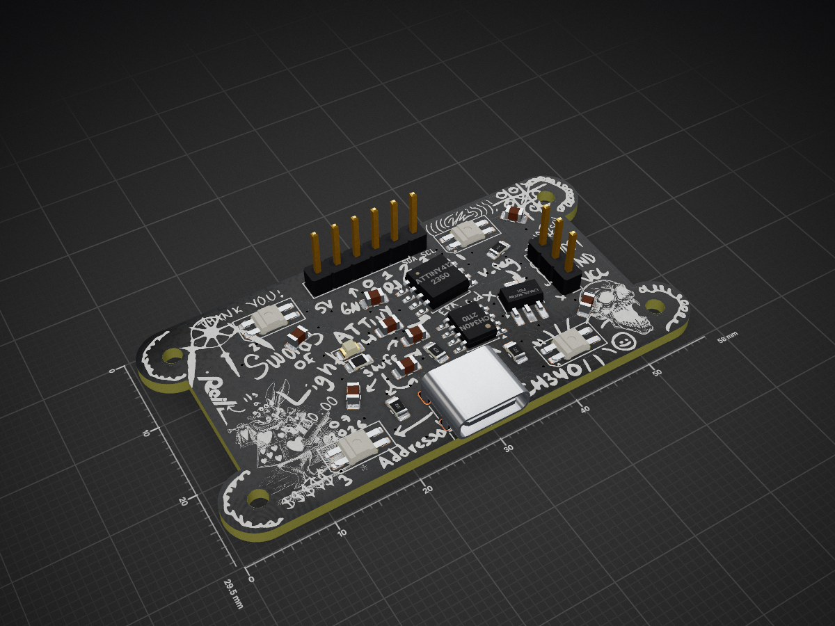
 user-will/cursedPCB1
A quick start guide and related files for the Cursed PCB by Reil Industrial
Attiny412 addressable is an open-source printed circuit board by user-will, from the user-will/cursedPCB repository on GitHub. It is a 2-layer board of 58 × 29.5 mm with 35 parts on 25 nets, routed with 227 tracks and 48 vias.
It is built around the ATTINY412-SSN, CH340N and SK6812MINI-E. Its parts include 8 capacitors, 5 resistors, 5 diodes, 3 ICs and 3 connectors. It belongs with the AVR (ATmega, ATtiny) boards of this library.


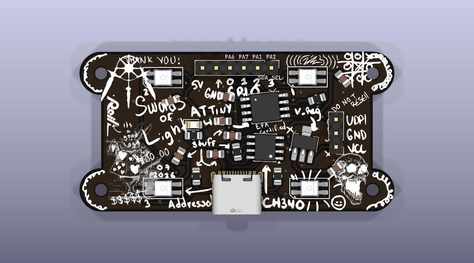
Cursed PCB is a programmable light board with an ATtiny412 microcontroller, four individually addressable RGB LEDs, onboard USB-C power, and an onboard CH340 SerialUPDI programmer. Plug it into a computer, install the ATtiny board support in Arduino IDE, and upload your own light patterns.
Quick links: LED example · megaTinyCore documentation
examples/LED_example/LED_example.ino — ready-to-upload LED animations and optional button supportattiny412_addressable.kicad_sch — KiCad schematicattiny412_addressable.kicad_pcb — KiCad PCB layoutattiny412_addressable.kicad_pro — KiCad project settings3d/attiny412_addressable_no_pin_headers.step — STEP assembly without the 1×6 and 1×3 pin headers3d/attiny412_addressable_no_pin_headers.wrl — VRML assembly without the 1×6 and 1×3 pin headersThe 3D exports include the PCB and modeled onboard components. J2 (the 1×6 GPIO header) and J3 (the 1×3 UPDI/power header) are intentionally unpopulated.
LED_example sketch in this repositoryNo separate LED library download is required. The tinyNeoPixel_Static library used by the example is included with megaTinyCore.
The ATtiny412 is not included in Arduino IDE by default. Install the megaTinyCore board package:
Open Arduino IDE.
Open File → Preferences. On macOS, open Arduino IDE → Settings.
Add this URL to Additional Boards Manager URLs:
http://drazzy.com/package_drazzy.com_index.jsonIf another URL is already present, use the button beside the field and add this URL on a new line.
Open Tools → Board → Boards Manager.
Search for megaTinyCore.
Install the newest version of megaTinyCore by Spence Konde.
The package includes the compiler, upload utility, and tinyNeoPixel libraries needed by this board.
Connect the board directly to the computer with a USB-C data cable. The power LED should turn on and a new serial port should appear in Arduino IDE.
Select these settings under Tools:
| Setting | Selection |
|---|---|
| Board | megaTinyCore → ATtiny412/402/212/202 |
| Clock | 20 MHz internal |
| BOD Voltage Level | 4.2V (20 MHz or less) |
| millis()/micros() Timer | Enabled (default timer) |
| Programmer | SerialUPDI - 230400 baud |
Choose the board entry without “w/Optiboot.” This board programs the ATtiny412 directly over UPDI and does not need a bootloader.
The onboard CH340 connection is dedicated to UPDI programming. It is not connected to the ATtiny412's normal UART pins, so Arduino Serial Monitor will not display Serial.print() output through this USB-C connection. PA6/TX and PA7/RX remain available on the six-pin header for an external serial adapter.
examples/LED_example/LED_example.ino in Arduino IDE.After the upload finishes, the four LEDs run through red, green, blue, white, a rainbow sweep, and a moving white chase.
The example supports an optional normally-open pushbutton connected between exposed pins 0 (PA6) and 2 (PA1). No external resistor is needed for this example: the sketch drives PA6 low and enables PA1's internal pull-up. Each press advances to the next animation.
If no button is connected, the example still works. It automatically shows the four solid colors and then continues with the rainbow sweep.
The four onboard LEDs are SK6812MINI-E addressable RGB LEDs connected as one chain. The first LED's data input is connected to PA3, which megaTinyCore calls Arduino pin 4.
The important setup from the example is:
#include <tinyNeoPixel_Static.h>

constexpr uint8_t LED_PIN = PIN_PA3;  // Arduino pin 4
constexpr uint8_t NUM_LEDS = 4;

byte pixelData[NUM_LEDS * 3];
tinyNeoPixel leds(NUM_LEDS, LED_PIN, NEO_GRB, pixelData);

void setup() {
  pinMode(LED_PIN, OUTPUT);
  leds.setBrightness(20);              // 0 to 255
  leds.setPixelColor(0, 255, 0, 0);   // first LED: red
  leds.show();
}
tinyNeoPixel_Static keeps the LED buffer in a fixed array, which is helpful on the ATtiny412's limited memory. Set colors with setPixelColor(), then call show() to send the updated buffer to the LEDs. The LEDs use NEO_GRB byte order.
Keep the brightness modest while experimenting. Four LEDs at full white use much more current and can be uncomfortably bright.
With the component side facing up and the USB-C connector at the bottom, the six-pin header reads left to right:
| Header label | Arduino pin | ATtiny412 pin | Common functions |
|---|---|---|---|
| 5V | — | VDD | Regulated 5 V rail/output — not an external power input |
| GND | — | GND | Ground |
| 0 | 0 | PA6 | Digital I/O, DAC, UART TX |
| 1 | 1 | PA7 | Digital I/O, UART RX |
| 2 | 2 | PA1 | Digital I/O, I²C SDA |
| 3 | 3 | PA2 | Digital I/O, I²C SCL |
Arduino pin 4 / PA3 controls the onboard LEDs and is not on the six-pin header. PA0 / UPDI is reserved for programming.
The separate three-pin header is labeled UPDI, GND, VCC from top to bottom when the USB-C connector is at the bottom. For standalone external power, connect the supply's positive lead to VCC and its negative lead to GND. VCC feeds the onboard voltage regulator. UPDI is for advanced external programming; none of these pins are needed for normal USB-C programming.
(VCC input − 5 V) × current. Keep external supply voltage and LED brightness as low as practical. Four LEDs at high or full-white brightness can exceed the regulator's 100 mA rating.NEO_GRB, and LED pin PIN_PA3 or Arduino pin 4.OUTPUT when using tinyNeoPixel_Static.setBrightness(20) slightly while testing, but do not start at full brightness.The ATtiny412 has 4 KB of program flash and 256 bytes of SRAM. Prefer tinyNeoPixel_Static, avoid large strings and unnecessary libraries, and keep the pixel buffer at 4 × 3 = 12 bytes.
For deeper ATtiny and library information, see the official megaTinyCore installation guide, megaTinyCore reference, and tinyNeoPixel reference.
| Qty | Value | Footprint | References |
|---|---|---|---|
| 6 | LOGO | LOGO | G***, G***, G***, G***, G***, G*** |
| 4 | 100nF | Capacitor_SMD:C_0805_2012Metric_Pad1.18x1.45mm_HandSolder | C3, C4, C5, C6 |
| 4 | MountingHole | MountingHole:MountingHole_2.2mm_M2 | H1, H2, H3, H4 |
| 4 | SK6812MINI-E | LED_SMD:LED_SK6812MINI-E_3.2x2.8mm_P1.5mm_ReverseMount | D6, D7, D8, D9 |
| 2 | 0.1uF | Capacitor_SMD:C_0805_2012Metric_Pad1.18x1.45mm_HandSolder | C2, C8 |
| 2 | 5.1K | Resistor_SMD:R_0805_2012Metric_Pad1.20x1.40mm_HandSolder | R2, R3 |
| 1 | 0.1uF_0603_16V | Capacitor_SMD:C_0805_2012Metric_Pad1.18x1.45mm_HandSolder | C1 |
| 1 | 10-47uF | Capacitor_SMD:C_0805_2012Metric_Pad1.18x1.45mm_HandSolder | C7 |
| 1 | 330R | Resistor_SMD:R_0805_2012Metric_Pad1.20x1.40mm_HandSolder | R4 |
| 1 | 4.7k | Resistor_SMD:R_0805_2012Metric_Pad1.20x1.40mm_HandSolder | R1 |
| 1 | ATtiny412 | Package_SO:SOIC-8_5.3x5.3mm_P1.27mm | U1 |
| 1 | CH340N | Package_SO:JEITA_SOIC-8_3.9x4.9mm_P1.27mm | U3 |
| 1 | GPIO Pins | Connector_PinHeader_2.54mm:PinHeader_1x06_P2.54mm_Vertical | J2 |
| 1 | L78L05_SOT89 | Package_TO_SOT_SMD:SOT-89-3_Handsoldering | U2 |
| 1 | LED | LED_SMD:LED_0805_2012Metric_Pad1.15x1.40mm_HandSolder | D5 |
| 1 | Power and Programming Pins | Connector_PinHeader_2.54mm:PinHeader_1x03_P2.54mm_Vertical | J3 |
| 1 | R_Small | Resistor_SMD:R_0805_2012Metric_Pad1.20x1.40mm_HandSolder | R5 |
| 1 | Solder Jumper | Jumper:SolderJumper-2_P1.3mm_Bridged_RoundedPad1.0x1.5mm | JP1 |
| 1 | USB_C_Receptacle_USB2.0_16P | Connector_USB:USB_C_Receptacle_Palconn_UTC16-G | J1 |
It measures 58 × 29.5 mm and has 2 copper layers, 1.6 mm thick.
35 parts, built around the ATTINY412-SSN, CH340N and SK6812MINI-E. The full list of its parts is on this page, with links to each part's symbol and footprint where PCBKit's library has them.
From the user-will/cursedPCB repository on GitHub, at the commit this page was made from: the board is attiny412_addressable.kicad_pcb and its schematic attiny412_addressable.kicad_sch. PCBKit opens the board in the browser, with nothing to install.
Its repository states no licence, so its author keeps all rights: ask user-will before reusing the design.
yansha2903-bot/LED-Keychain
A small programmable LED keychain designed in KiCad and powered by an ATtiny412.


fijam/md-lpm
This project consists of hardware files and software for a coin-battery operated laser tester that fits in a MiniDisk case.


Fab-Lab-Island/fli-bootcamp-2025
About Fab Lab ísland bootcamp Húsavík 2025. Kíkið á síðuna fyrir neðan!

Brasseur2robot/Les-brasseurs-d-idees
Codebase de l'équipe légende des brasseurs d'idées concourant à la coupe de France de robotique. Vous pouvez y retrouver les différents fichiers utilisés pour la création et le fonctionnement de notre robot principal et…

SreeniEadara/Hopkins-iGEM-2022-electrical
Schematics and PCB designs for Hopkins iGEM 2022
