2 layers44.5 × 46.9 mm
OSO SWAT B1-jig
joeycastillo/Sensor-Watch
A board replacement for the classic Casio F-91W wristwatch
31 parts2.1k

 Usagimimi/zigbeebox1
Powerful zigbee coordinator with USB and debug port in metal enclosure.
Zigbeebox is an open-source printed circuit board by Usagimimi, from the Usagimimi/zigbeebox repository on GitHub, published under the GPL-3.0 licence. It is a 2-layer board of 79.7 × 47.1 mm with 31 parts on 47 nets, routed with 232 tracks and 13 vias.
Its parts include 9 resistors, 5 capacitors, 3 diodes, 2 connectors and 1 IC. It belongs with the radio and wireless boards of this library.
Powerful zigbee coordinator with USB and debug port in metal enclosure.
The coordinator is the central unit of the zigbee network, handling significant RF traffic in most cases. This project offers low-cost open-source hardware for this task, as a remix of many DIY coordinators out there. Takes a bit of time and basic soldering skills to assemble, but it can replace any manufacturers proprietary device when ready. Using the right firmware and server application, you can build a reliable, secure zigbee network without factory restrictions, involving almost any zigbee appliance. This opens the possibility to use IKEA Tradfri lights along with Xiaomi sensors, Philips Hue products, and many more in the same network, without the vendors gateway. The pcb utilizes a cheap chinese CC2538+CC2592 RF module with ARM Cortex-M3 based SoC and enough memory to serve a lot of connections with good performance.
The design heavily relies on open-source code, such as Zigbee2MQTT and various firmware.
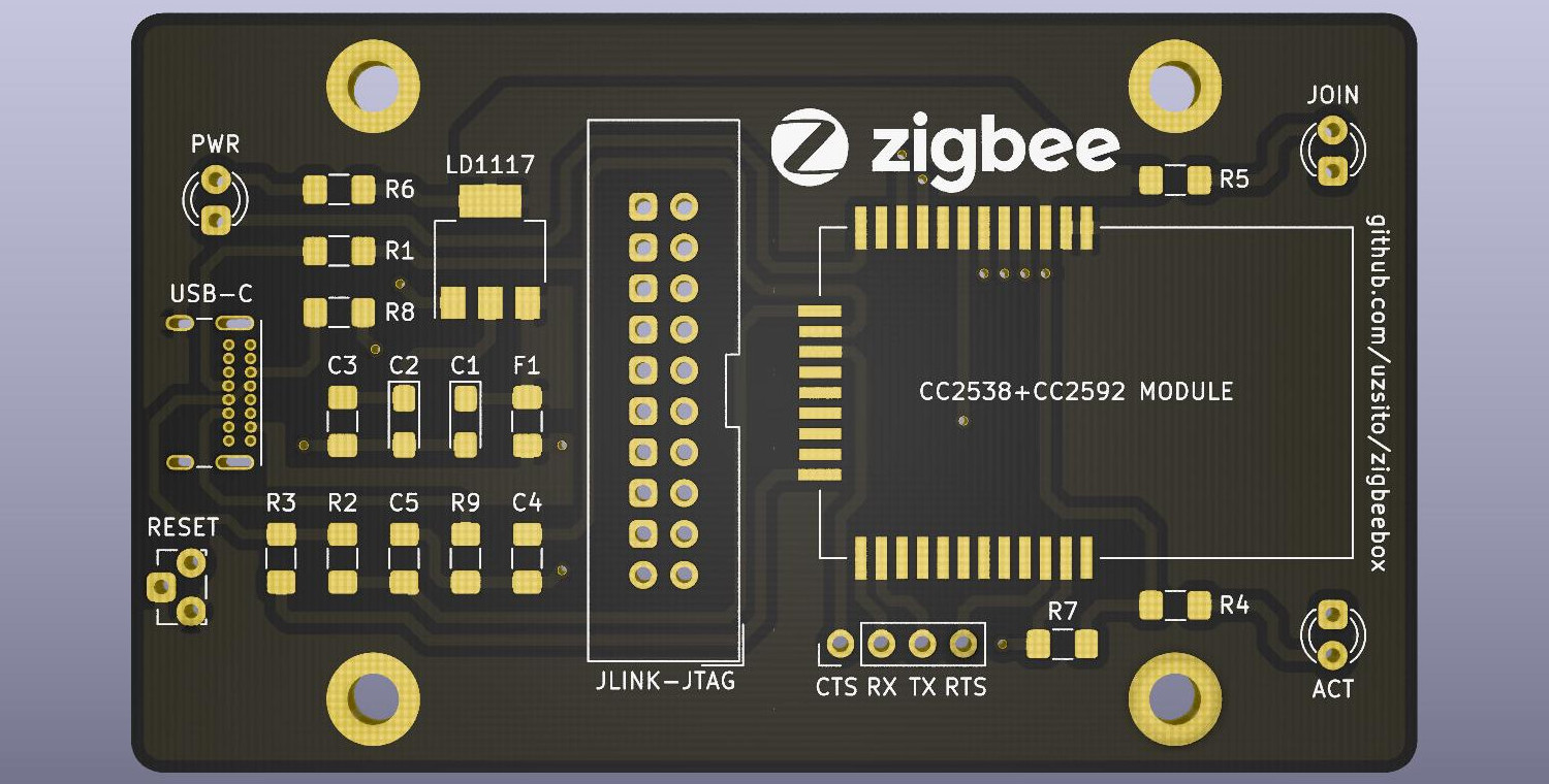
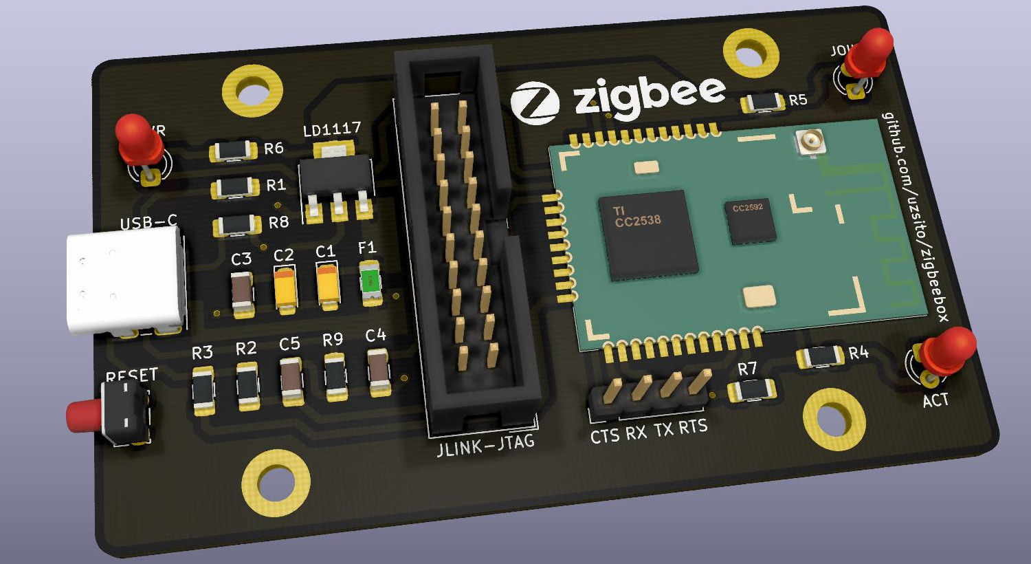
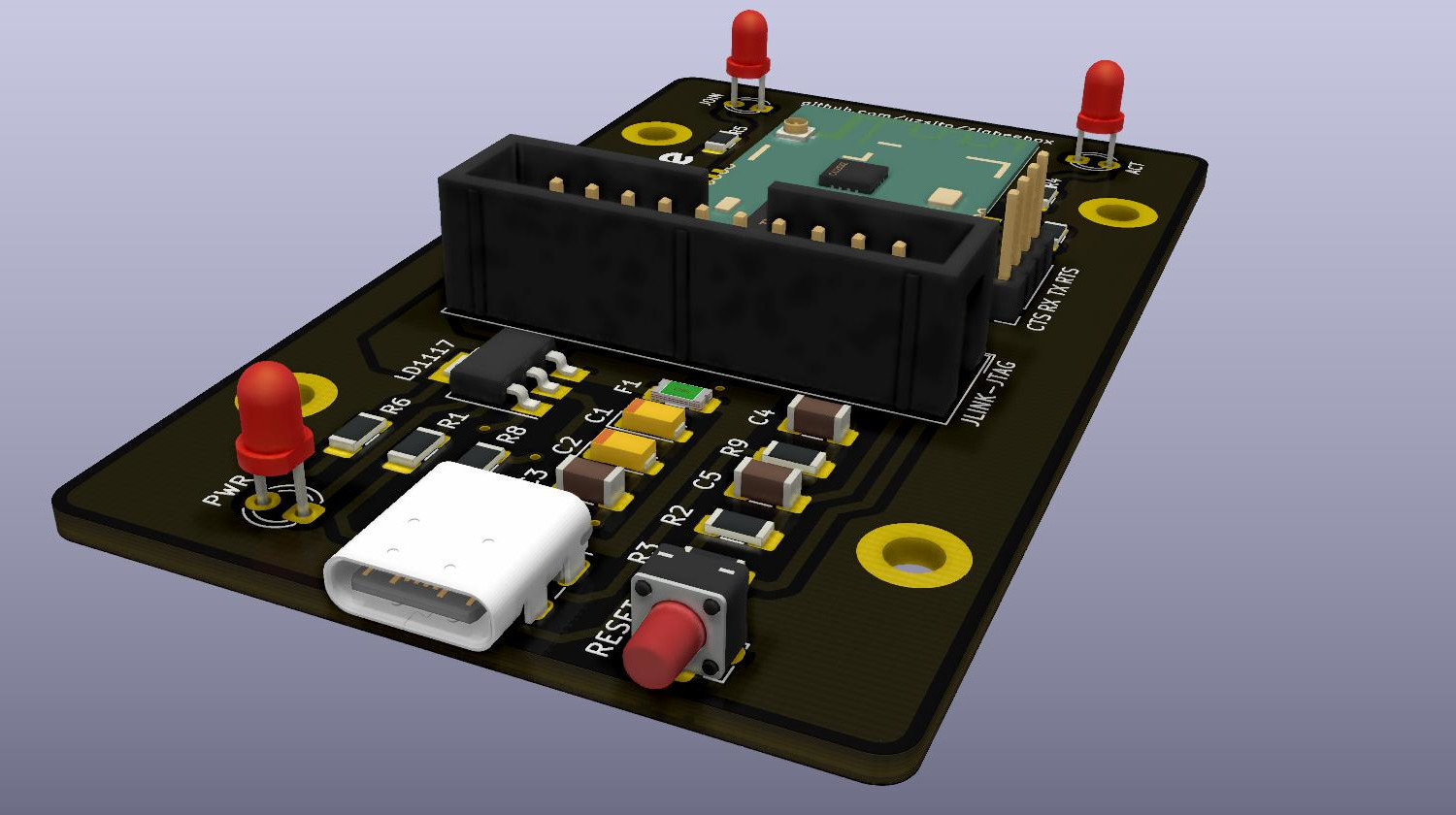
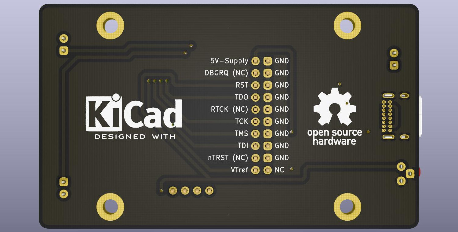
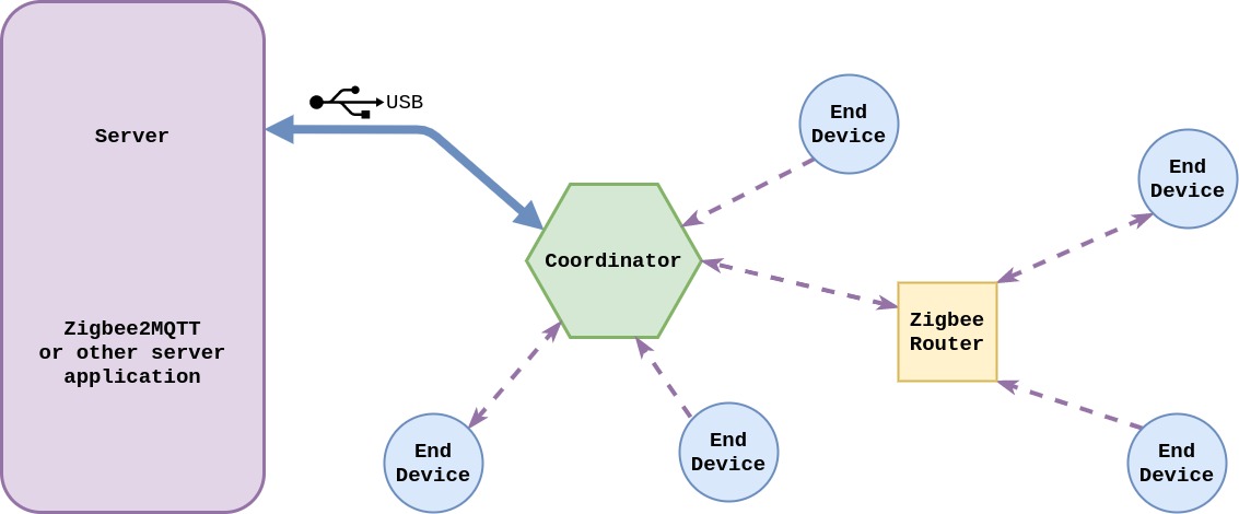
Since the pcb applies a considerable amount of copper under the CC2538+CC2592 module, it is highly recommended to use the IPEX connector and connect an external antenna, even without metal enclosure.
The following components are needed to assemble the coordinator.
| Component | Type | Package | Value | Quantity |
|---|---|---|---|---|
| F1 | Polyfuse | SMD-1206 | Ih=250mA, It=500mA | 1 |
| R1-R2 | Resistor | SMD-1206 | 33Ω | 2 |
| R3 | Resistor | SMD-1206 | 1.5kΩ | 1 |
| R4-R6 | Resistor | SMD-1206 | 100Ω | 3 |
| R7 | Resistor | SMD-1206 | 1kΩ | 1 |
| R8-R9 | Resistor | SMD-1206 | 5.1kΩ | 2 |
| C1-C2 | Tantalum capacitor | SMD-1206 | 10uF | 2 |
| C3 | Capacitor | SMD-1206 | 100nF | 1 |
| C4-C5 | Capacitor | SMD-1206 | 47pF | 2 |
| PWR-JOIN-ACT | LED | 3mm THT | Vf=2.2V, If=10mA | 3 |
| LD1117 | Voltage regulator | SOT223 | LD1117S33TR | 1 |
| USB-C | Receptacle | 16-pin THT | GCT USB4085 | 1 |
| RESET | Tactile switch | 3-pin THT 4.5x4.5mm | TS-C017 | 1 |
| JLINK-JTAG | Connector | 2.54mm IDC double row | 20-pin keyed male | 1 |
| Pin header | Connector | 2.54mm single row | 4-pin male | 1 |
Additional parts:
| Component | Type | Package | Quantity | Source |
|---|---|---|---|---|
| CC2538+CC2592 Module | Zigbee RF board | 33-pin 20.5x33mmm | 1 | Aliexpress, Ebay |
You can download and burn compiled firmware from the following repositories:
| Repository | Firmware | Tested |
|---|---|---|
| reverieline/CC2538-CC2592-ZNP | MODKAMRU_V3_USB.hex | Tested |
| antst/CC2538-ZNP-Coordinator-firmware | Not tested | |
| Koenkk/Z-Stack-firmware | Not tested |
Flashing methods:
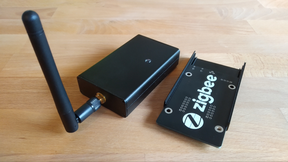
It is optional to put the board in a cheap metal case to achieve better shielding and appearance. The finished pcb fits perfectly in a common box by design, with an applied pigtail to connect your external antenna.
Finished photos and cutout templates coming soon.
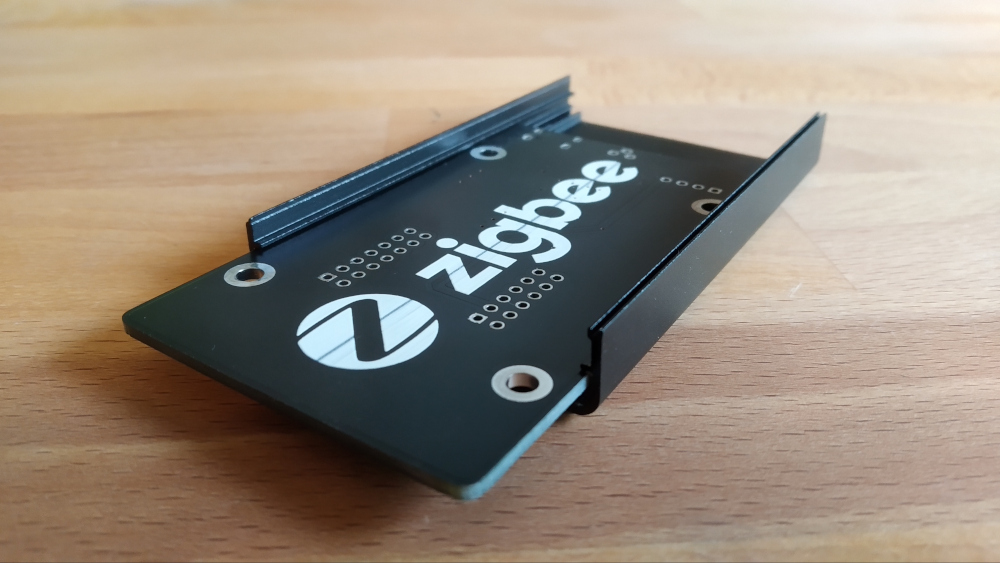
Former prototype:
| Qty | Value | Footprint | References |
|---|---|---|---|
| 4 | MountingHole_Pad | MountingHole:MountingHole_3.2mm_M3_ISO7380_Pad | H1, H2, H3, H4 |
| 3 | 100R | Resistor_SMD:R_1206_3216Metric_Pad1.42x1.75mm_HandSolder | R4, R5, R6 |
| 2 | 10uF | Capacitor_Tantalum_SMD:CP_EIA-3216-12_Kemet-S_Pad1.58x1.35mm_HandSolder | C1, C2 |
| 2 | 33R | Resistor_SMD:R_1206_3216Metric_Pad1.42x1.75mm_HandSolder | R1, R2 |
| 2 | 47pF | Capacitor_SMD:C_1206_3216Metric_Pad1.42x1.75mm_HandSolder | C4, C5 |
| 2 | 5.1k | Resistor_SMD:R_1206_3216Metric_Pad1.42x1.75mm_HandSolder | R8, R9 |
| 1 | 1.5K | Resistor_SMD:R_1206_3216Metric_Pad1.42x1.75mm_HandSolder | R3 |
| 1 | 100nF | Capacitor_SMD:C_1206_3216Metric_Pad1.42x1.75mm_HandSolder | C3 |
| 1 | 1k | Resistor_SMD:R_1206_3216Metric_Pad1.42x1.75mm_HandSolder | R7 |
| 1 | ACT | LED_THT:LED_D3.0mm | LED1 |
| 1 | CC2538+CC2592 MODULE | RF_Module:CC2538_CC2592 | U1 |
| 1 | Debug | Connector_PinHeader_2.54mm:PinHeader_1x04_P2.54mm_Vertical | J1 |
| 1 | Fuse | Fuse:Fuse_1206_3216Metric_Pad1.42x1.75mm_HandSolder | F1 |
| 1 | JLINK-JTAG | Connector_IDC:IDC-Header_2x10_P2.54mm_Vertical | J2 |
| 1 | JOIN | LED_THT:LED_D3.0mm | LED2 |
| 1 | LD1117S33TR_SOT223 | Package_TO_SOT_SMD:SOT-223-3_TabPin2 | LD1117 |
| 1 | LOGO | Symbol:zigbee_logo | G*** |
| 1 | PWR | LED_THT:LED_D3.0mm | LED3 |
| 1 | RESET | Button_Switch_THT:SW_Tactile_PUSH_Angled_4.5mm_H6.0mm_TS_C017 | SW1 |
| 1 | USB-C | Connector_USB:USB_C_Receptacle_GCT_USB4085 | USB1 |
The 29 most common of 31 parts.
It measures 79.7 × 47.1 mm and has 2 copper layers, 1.6 mm thick.
31 parts. The full list of its parts is on this page, with links to each part's symbol and footprint where PCBKit's library has them.
From the Usagimimi/zigbeebox repository on GitHub, at the commit this page was made from: the board is kicad_board/zigbeebox.kicad_pcb. PCBKit opens the board in the browser, with nothing to install.
Its repository publishes it under the GPL-3.0 licence: you may reuse it on that licence's terms (keep the author's notice, and for a copyleft licence share your changes alike).
joeycastillo/Sensor-Watch
A board replacement for the classic Casio F-91W wristwatch

hoglet67/RGBtoHDMI
Bare-metal Raspberry Pi project that provides pixel-perfect sampling of Retro Computer RGB/YUV video and conversion to HDMI

hackclub/OnBoard
💡 Join 1,000 teenagers and make your first PCB with a $100 grant!

openwch/ch32v003
CH32V003 is an ultra-cheap RISC-V MCU with 2KB SRAM, 16KB flash, and up to 18 GPIOs that sells for under $0.10

Luos-io/luos_engine
Open-source and real-time orchestrator for cyber-physical-systems, to easily design, test and deploy embedded applications and digital twins.

BlueAndi/Pixelix
Full RGB LED matrix, based on an ESP32 and WS2812B LEDs or emulated LEDs on TFT.

