
2 layers
Smartwatch
alexew0923/Smartwatch
A custom smartwatch built with 1.28 inch round TFT touchscreen display and ESP32
25 parts

 UPM-SPV/pcb
Coin-cell powered BLE weather station with nRF54L15. Measuring temperature, humidity, air quality, luminosity, and noise.
Sensor node is an open-source printed circuit board by UPM-SPV, from the UPM-SPV/pcb repository on GitHub, published under the CERN-OHL-S-2.0 licence. It is a 4-layer board of 55 × 28 mm with 72 parts on 51 nets, routed with 292 tracks and 81 vias.
It is built around the NRF54L15-QFAA-R, SHTC3 and VEML6035, with the CR2450 among its other parts. Its parts include 21 capacitors, 8 resistors, 5 ICs, 4 inductors and 2 connectors. It belongs with the home automation and IoT and sensors and measurement boards and the nRF52 and nRF5x boards of this library.


 |  |
|---|
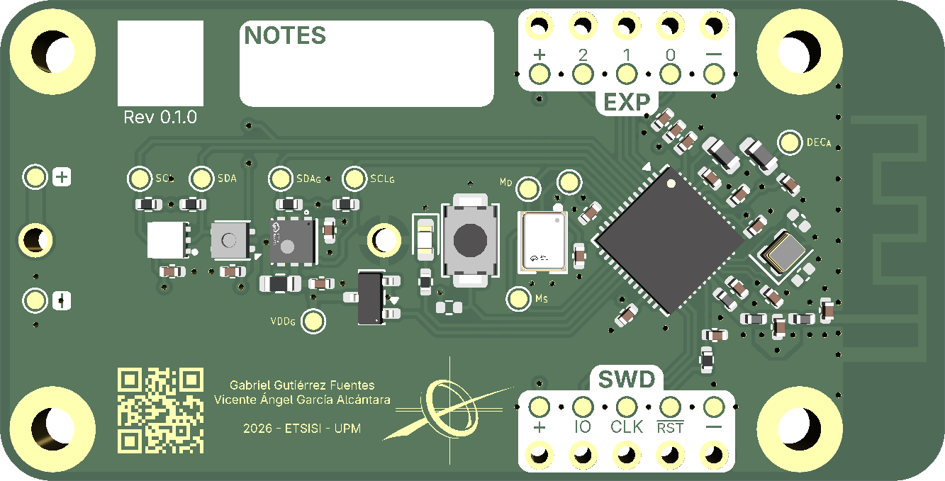
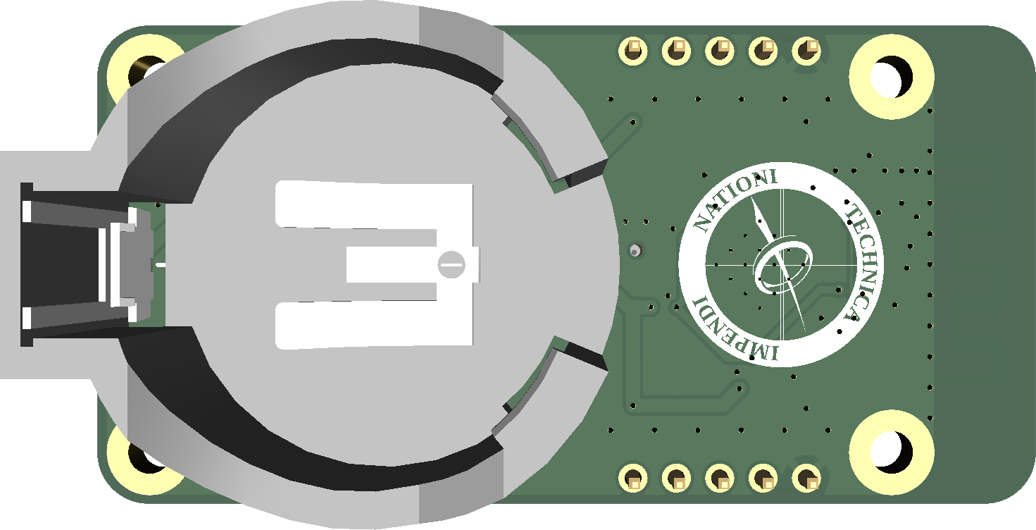
This is the PCB I designed for my undergrad thesis. It's a four-layer board consisting of an nRF54L15, multiple environmental sensors, an LED, and a button, all powered by a single CR2450 battery on the back.
The board has 4 sensors in total:
The board is intended to be a cheap weather station. It can be programmed to collect and store data periodically, and then send it over BLE to a smartphone via the nRF54L15 microcontroller.
The thesis firmware implements this exact functionality.
The board was mostly designed to keep costs as low as possible. The board can be assembled with JLCPCB's basic assembly, and the majority of the components are in JLCPCB's basic lineup (except the ICs and some passives).
The total cost for a low-volume order is around €16.68 per board and €33.52 for the setup fee. Do keep in mind that JLC's basic library changes over time, so this price may change (and probably already has).
If you intend on ordering this board, keep in mind that it has some design errors. They are mostly inconsequential and easy to fix and may not even affect you, but still:
Push-button does not support interrupts: probably the most important. The button is connected to P2.05, since the MCU power domain of the nRF54L series does not support interrupts, neither does said pin. The fix is to simply re-route it to any of the other pins (P0 or P1).
LED doesn't support PWM: again, the P2 pins do not have any advanced I/O peripherals, and so the LED can only be toggled on and off, but not dimmed. Re-reoute it to any of the P1 pins (where the GRTC peripheral is) to fix it.
Mounting holes are connected to ground: if you intend on using this outside with a 3D-printed case, using metallic screws could corrode the PCB. Modify the mounting holes so they're covered in solder mask to avoid this. Can be ignored if used indoors.
Silkscreen is unreadable in some instances: the silkscreen text (and solder mask punch-out) is too small and comes out blurry when ordering from JLCPCB. You can probably ignore this, but if it bothers you, make the text bigger.
I'm waiting on a scholarship and currently working on a second revision, so these will be fixed eventually.
This repository and all of its files are released under the CERN Open Hardware Licence Version 2 - Strongly Reciprocal license.
Copyright (c) Gabriel Gutiérrez Fuentes 2026
| Qty | Value | Footprint | References |
|---|---|---|---|
| 7 | 100nF | Capacitor_SMD:C_0402_1005Metric | C3, C4, C5, C8, C9, C10, C11 |
| 4 | 47kΩ | Resistor_SMD:R_0402_1005Metric | R1, R2, R3, R4 |
| 3 | GND | TestPoint:TestPoint_Pad_D1.0mm | TP6, TP15, TP22 |
| 3 | VDD | TestPoint:TestPoint_Pad_D1.0mm | TP2, TP14, TP21 |
| 2 | 10uF | Capacitor_SMD:C_0402_1005Metric | C6, C7 |
| 2 | 1kΩ | Resistor_SMD:R_0402_1005Metric | R6, R8 |
| 2 | 1uF | Capacitor_SMD:C_0402_1005Metric | C1, C2 |
| 2 | 2.2uF | Capacitor_SMD:C_0402_1005Metric | C14, C18 |
| 2 | 3.5nH | Inductor_SMD:L_0402_1005Metric | L3, L4 |
| 2 | TBD | Capacitor_SMD:C_0402_1005Metric | C12, C13 |
| 1 | 0.3pF | Capacitor_SMD:C_0402_1005Metric | C17 |
| 1 | 1.5pF | Capacitor_SMD:C_0402_1005Metric | C15 |
| 1 | 10nF | Capacitor_SMD:C_0402_1005Metric | C19 |
| 1 | 120Ω @ 100MHz | Inductor_SMD:L_0603_1608Metric | FB1 |
| 1 | 1nF | Capacitor_SMD:C_0402_1005Metric | C20 |
| 1 | 2.0pF | Capacitor_SMD:C_0402_1005Metric | C16 |
| 1 | 2.7nH | Inductor_SMD:L_0402_1005Metric | L2 |
| 1 | 32MHz | Crystal:Crystal_SMD_2016-4Pin_2.0x1.6mm | Y1 |
| 1 | 4.7pF | Capacitor_SMD:C_0402_1005Metric | C21 |
| 1 | 4.7uH | Inductor_SMD:L_0603_1608Metric | L1 |
| 1 | 4.7Ω | Resistor_SMD:R_0603_1608Metric | R5 |
| 1 | BL | MountingHole:MountingHole_2.5mm_Pad | H3 |
| 1 | BR | MountingHole:MountingHole_2.5mm_Pad | H4 |
| 1 | CR2450 | Footprints:CR2450 | BT2 |
| 1 | DEC_{RF} | TestPoint:TestPoint_Pad_D1.0mm | TP20 |
| 1 | EXP | Connector_PinHeader_2.54mm:PinHeader_1x05_P2.54mm_Vertical | J3 |
| 1 | EXP_{0} | TestPoint:TestPoint_Pad_D1.0mm | TP16 |
| 1 | EXP_{1} | TestPoint:TestPoint_Pad_D1.0mm | TP17 |
| 1 | EXP_{2} | TestPoint:TestPoint_Pad_D1.0mm | TP18 |
| 1 | IM70D122 | Footprints:IM70D122 | U4 |
| 1 | LED | LED_SMD:LED_0603_1608Metric | D1 |
| 1 | MIC_{CLK} | TestPoint:TestPoint_Pad_D1.0mm | TP12 |
| 1 | MIC_{DATA} | TestPoint:TestPoint_Pad_D1.0mm | TP13 |
| 1 | MIC_{SEL} | TestPoint:TestPoint_Pad_D1.0mm | TP11 |
| 1 | PMOS | Footprints:SOT-23 | Q1 |
| 1 | SCL | TestPoint:TestPoint_Pad_D1.0mm | TP10 |
| 1 | SCL_{G} | TestPoint:TestPoint_Pad_D1.0mm | TP8 |
| 1 | SDA | TestPoint:TestPoint_Pad_D1.0mm | TP9 |
| 1 | SDA_{G} | TestPoint:TestPoint_Pad_D1.0mm | TP7 |
| 1 | SGP40 | Footprints:SGP40 | U1 |
| 1 | SHTC3 | Footprints:SHTC3 | U2 |
| 1 | SWD | Connector_PinHeader_2.54mm:PinHeader_1x05_P2.54mm_Vertical | J1 |
| 1 | SWD_{CLK} | TestPoint:TestPoint_Pad_D1.0mm | TP4 |
| 1 | SWD_{IO} | TestPoint:TestPoint_Pad_D1.0mm | TP5 |
| 1 | SWRA117D | RF_Antenna:Texas_SWRA117D_2.4GHz_Left | ANT1 |
| 1 | TBD | Resistor_SMD:R_0402_1005Metric | R7 |
| 1 | TL | MountingHole:MountingHole_2.5mm_Pad | H1 |
| 1 | TR | MountingHole:MountingHole_2.5mm_Pad | H2 |
| 1 | USR | Button_Switch_SMD:SW_SPST_TS-1088-xR020 | SW1 |
| 1 | VDD_{G} | TestPoint:TestPoint_Pad_D1.0mm | TP1 |
| 1 | VEML6035 | Footprints:VEML6035 | U3 |
| 1 | nRF54L15-QFAA | Package_DFN_QFN:QFN-48-1EP_6x6mm_P0.4mm_EP4.6x4.6mm_ThermalVias | U5 |
| 1 | ~{RESET} | TestPoint:TestPoint_Pad_D1.0mm | TP3 |
It measures 55 × 28 mm and has 4 copper layers, 1.65 mm thick.
72 parts, built around the NRF54L15-QFAA-R, SHTC3, VEML6035 and CR2450. The full list of its parts is on this page, with links to each part's symbol and footprint where PCBKit's library has them.
From the UPM-SPV/pcb repository on GitHub, at the commit this page was made from: the board is sensor_node.kicad_pcb and its schematic nrf54l15.kicad_sch. PCBKit opens the board in the browser, with nothing to install.
Its repository publishes it under the CERN-OHL-S-2.0 licence: you may reuse it on that licence's terms (keep the author's notice, and for a copyleft licence share your changes alike).
alexew0923/Smartwatch
A custom smartwatch built with 1.28 inch round TFT touchscreen display and ESP32


lime7git/heart
A small gift. Heart shape PCB with STM32L0 microcontroller, gpio expander, accelerometer and some fancy leds.


DAWN-cxx/smart-temp-humidity-sensor-pro-pcb
A 4-layer low-power BLE temperature and humidity sensor PCB designed with KiCad 8.0.