2 layers70 × 60 mm

 UofC-GNCTR-2024/Claw-Machine-PCB1
PCB for the UofC GNCTR 2024 claw machine game
Claw machine is an open-source printed circuit board by UofC-GNCTR-2024, from the UofC-GNCTR-2024/Claw-Machine-PCB repository on GitHub, published under the MIT licence. It is a 2-layer board of 162.6 × 133.4 mm with 114 parts on 123 nets, routed with 995 tracks and 79 vias.
It is built around the L298N and AO3400A. Its parts include 38 connectors, 25 resistors, 14 capacitors, 7 diodes and 4 transistors. It belongs with the AVR (ATmega, ATtiny) boards of this library.


PCB for the UofC GNCTR 2024 claw machine
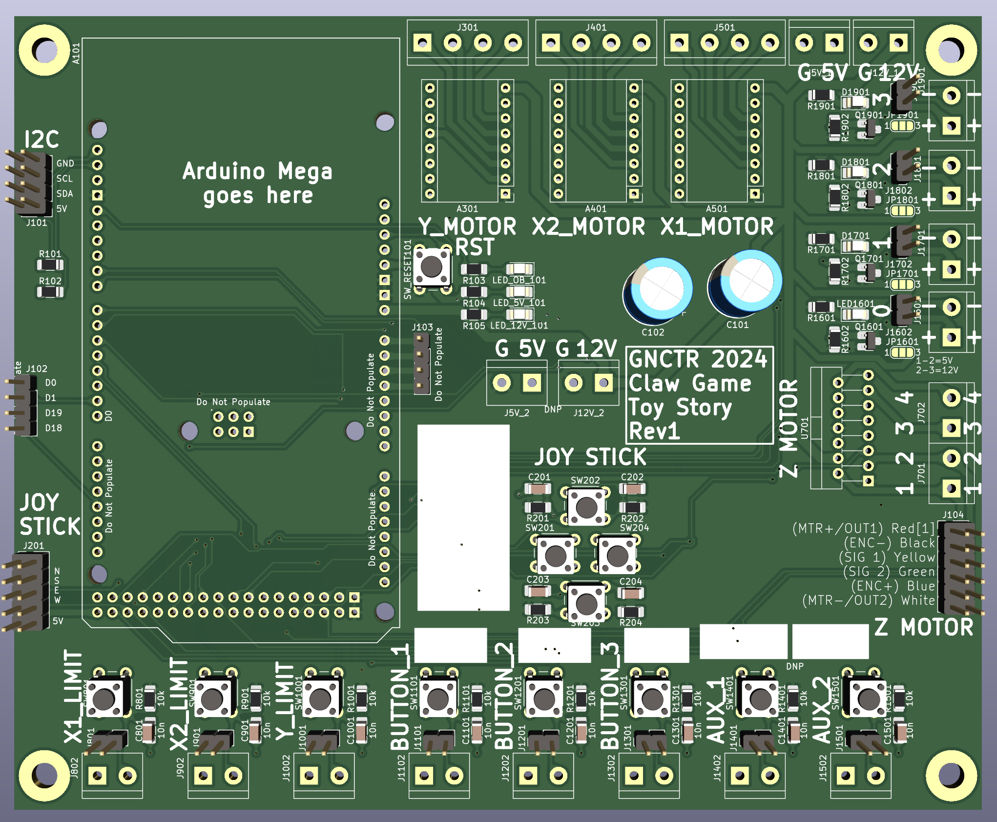
3x Stepper Motor Drivers
1x DC Motor Driver
Countdown Clock I2C Connector
10x Buttons and Limit Switches
Control Stick
1x Microcontroller System
4x General Power Output Channels
Voltage Input Rails
| Qty | Value | Footprint | References |
|---|---|---|---|
| 18 | Screw_Terminal_01x02 | TerminalBlock:TerminalBlock_bornier-2_P5.08mm | J5V_1, J5V_2, J12V_1, J12V_2, J701, J702, J1002, J1102, J1202, J1302, J1402, J1502, J1601, J1701, J1801, J1901 +2 |
| 17 | 10k | Resistor_SMD:R_1206_3216Metric_Pad1.30x1.75mm_HandSolder | R105, R201, R202, R203, R204, R801, R1001, R1101, R1201, R1301, R1401, R1501, R1602, R1702, R1802, R1902 +1 |
| 13 | SW_Push | Button_Switch_THT:SW_PUSH_6mm | SW_RESET101, SW201, SW202, SW203, SW204, SW801, SW901, SW1001, SW1101, SW1201, SW1301, SW1401, SW1501 |
| 12 | 10n | Capacitor_SMD:C_1206_3216Metric_Pad1.33x1.80mm_HandSolder | C201, C202, C203, C204, C801, C901, C1001, C1101, C1201, C1301, C1401, C1501 |
| 12 | Conn_01x02 | Connector_PinHeader_2.54mm:PinHeader_1x02_P2.54mm_Vertical | J801, J901, J1001, J1101, J1201, J1301, J1401, J1501, J1602, J1702, J1802, J1902 |
| 7 | LED | LED_SMD:LED_1206_3216Metric_Pad1.42x1.75mm_HandSolder | D1701, D1801, D1901, LED_5V_101, LED_12V_101, LED_OB_101, LED1601 |
| 6 | 2k2 | Resistor_SMD:R_1206_3216Metric_Pad1.30x1.75mm_HandSolder | R103, R104, R1601, R1701, R1801, R1901 |
| 4 | AO3400A | Library:SOT-23-MassivePads-HandSolder | Q1601, Q1701, Q1801, Q1901 |
| 4 | MountingHole | MountingHole:MountingHole_4.3mm_M4_Pad_TopBottom | H101, H102, H103, H104 |
| 4 | SolderJumper_3_Open | Jumper:SolderJumper-3_P1.3mm_Open_RoundedPad1.0x1.5mm_NumberLabels | JP1601, JP1701, JP1801, JP1901 |
| 3 | Pololu_Breakout_A4988 | Module:Pololu_Breakout-16_15.2x20.3mm | A301, A401, A501 |
| 3 | Screw_Terminal_01x04 | TerminalBlock:TerminalBlock_bornier-4_P5.08mm | J301, J401, J501 |
| 2 | 100u | Capacitor_THT:CP_Radial_D10.0mm_P5.00mm_P7.50mm | C101, C102 |
| 2 | 3k3 | Resistor_SMD:R_1206_3216Metric_Pad1.30x1.75mm_HandSolder | R101, R102 |
| 2 | Conn_01x04 | Connector_PinHeader_2.54mm:PinHeader_1x04_P2.54mm_Vertical | J102, J103 |
| 1 | Arduino_Mega2560_R3_Shield | PCM_arduino-library:Arduino_Mega2560_R3_Shield | A101 |
| 1 | Conn_02x05_Odd_Even | Connector_PinHeader_2.54mm:PinHeader_2x05_P2.54mm_Vertical | J201 |
| 1 | Conn_02x06_Odd_Even | Connector_PinHeader_2.54mm:PinHeader_2x06_P2.54mm_Vertical | J104 |
| 1 | L298N | Package_TO_SOT_THT:TO-220-15_P2.54x2.54mm_StaggerOdd_Lead4.58mm_Vertical | U701 |
| 1 | ~ | Connector_PinHeader_2.54mm:PinHeader_2x04_P2.54mm_Vertical | J101 |


pedro-ibs/trekking
Desenvolvimento de um robô rádio-controlado/autônomo da moralidade “tracker”

FabioNMI/C64PSU
A low-cost, lightweight and very reliable power supply for the Commodore 64

Khuzhin06/RoboForce
Тогда вы не зря зашли к нам, мы постараемся максимально подробно и быстро рассказать о нашем пути создания робота на ROS2 Jazzy и esp32,по этим материалам вы с легкостью сможете повторить этот проект.


CainPatel/diy-ert
A $150 four-electrode earth resistivity meter (Wenner array): Arduino, AD620, ADS1115. Documented failure-first as an engineering log.

dduarteCE/Robot-vacuum
Embedded Linux robotic vacuum system built with Yocto on Raspberry Pi 4, featuring autonomous navigation, audio playback, and remote control through a web interface.
It measures 162.6 × 133.4 mm and has 2 copper layers, 1.6 mm thick.
114 parts, built around the L298N and AO3400A. The full list of its parts is on this page, with links to each part's symbol and footprint where PCBKit's library has them.
From the UofC-GNCTR-2024/Claw-Machine-PCB repository on GitHub, at the commit this page was made from: the board is claw_machine/claw_machine.kicad_pcb and its schematic claw_machine/claw_machine.kicad_sch. PCBKit opens the board in the browser, with nothing to install.
Its repository publishes it under the MIT licence: you may reuse it on that licence's terms (keep the author's notice, and for a copyleft licence share your changes alike).