
2 layers134 × 88 mm
Tulipcc
shorepine/tulipcc
The Tulip Creative Computer and AMYboard - portable Python synthesizers
103 parts978

 unixvoid/squidgrip
squidgrip auto-reset ESP32 flasher based on a CP2102N
Squidgrip is an open-source printed circuit board by unixvoid, from the unixvoid/squidgrip repository on GitHub. It is a 2-layer board of 42.8 × 19 mm with 28 parts on 35 nets, routed with 155 tracks and 31 vias.
It is built around the MBT3904DW1T1G-HXY. Its parts include 8 resistors, 3 capacitors, 3 ICs, 3 diodes and 2 switches.
Squidgrip is a clamp-on USB-UART probe for programming ESP32 boards. It is a CP2102N on a small USB-C board with a 6-pin pogo pin array on a thin tongue, plus a 3D printed clamp that presses that tongue onto the programming pads of a target board.
It carries the ESP32 auto-reset circuit, so esptool, the ExpressLRS Configurator, PlatformIO, Arduino IDE, etc can drop a target into the bootloader and flash it without you touching anything. There are RESET and BOOT buttons for doing it by hand, power/TX/RX LEDs, and a 3.3 V LDO so the probe can power the board it is flashing.
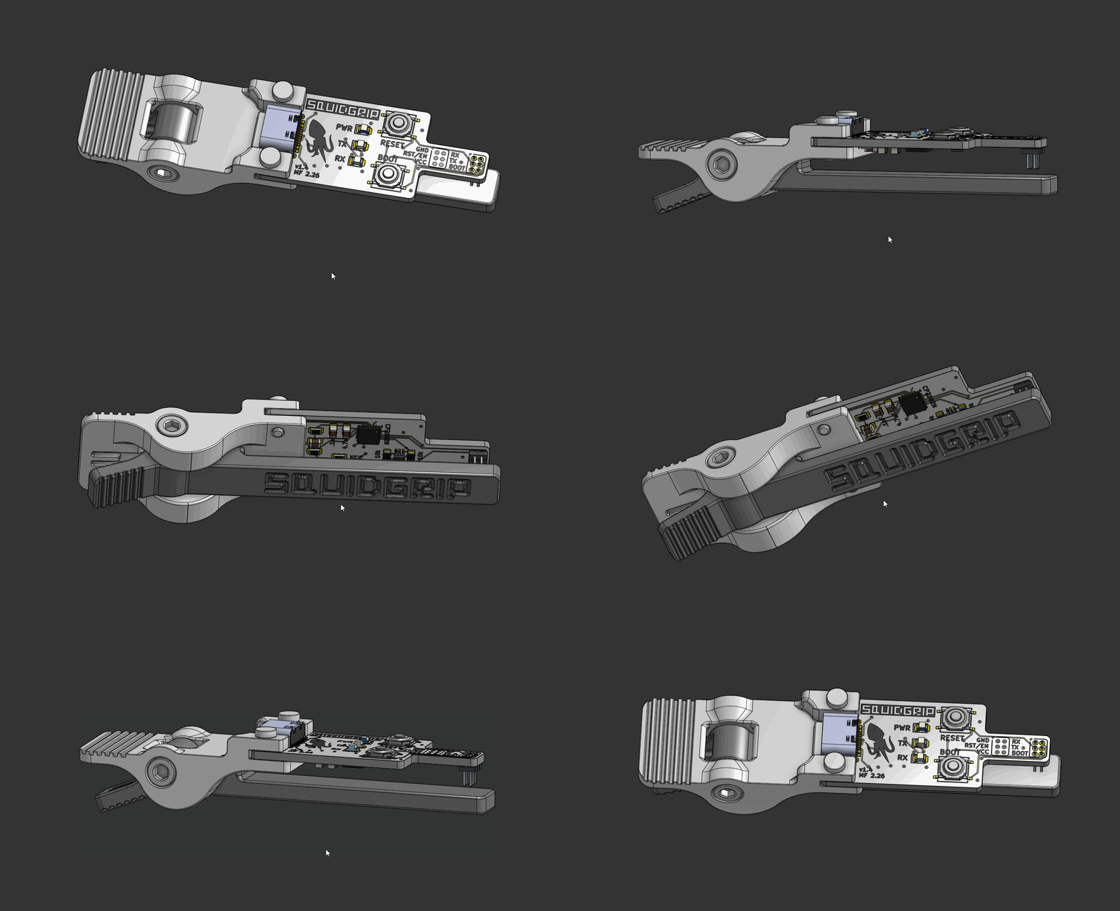
squidgrip in the clamp (3D render)
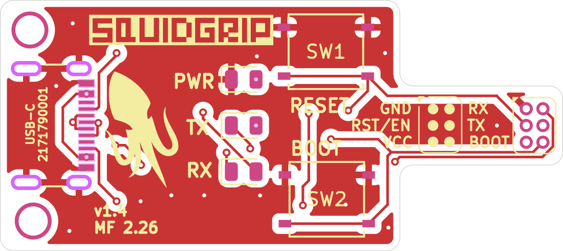
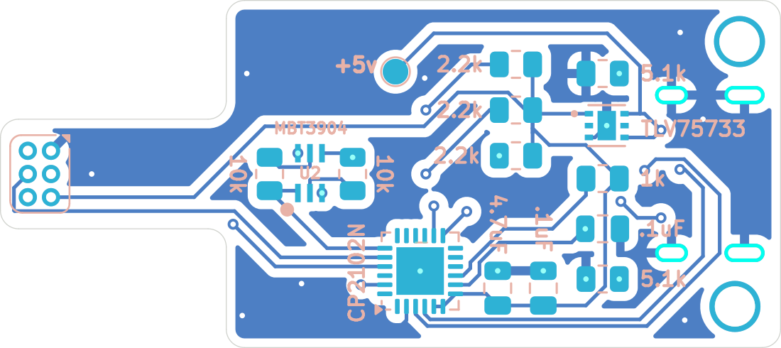
Copper and silkscreen: front and rear
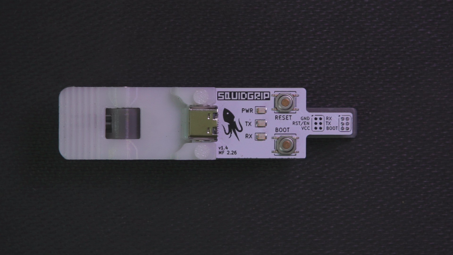
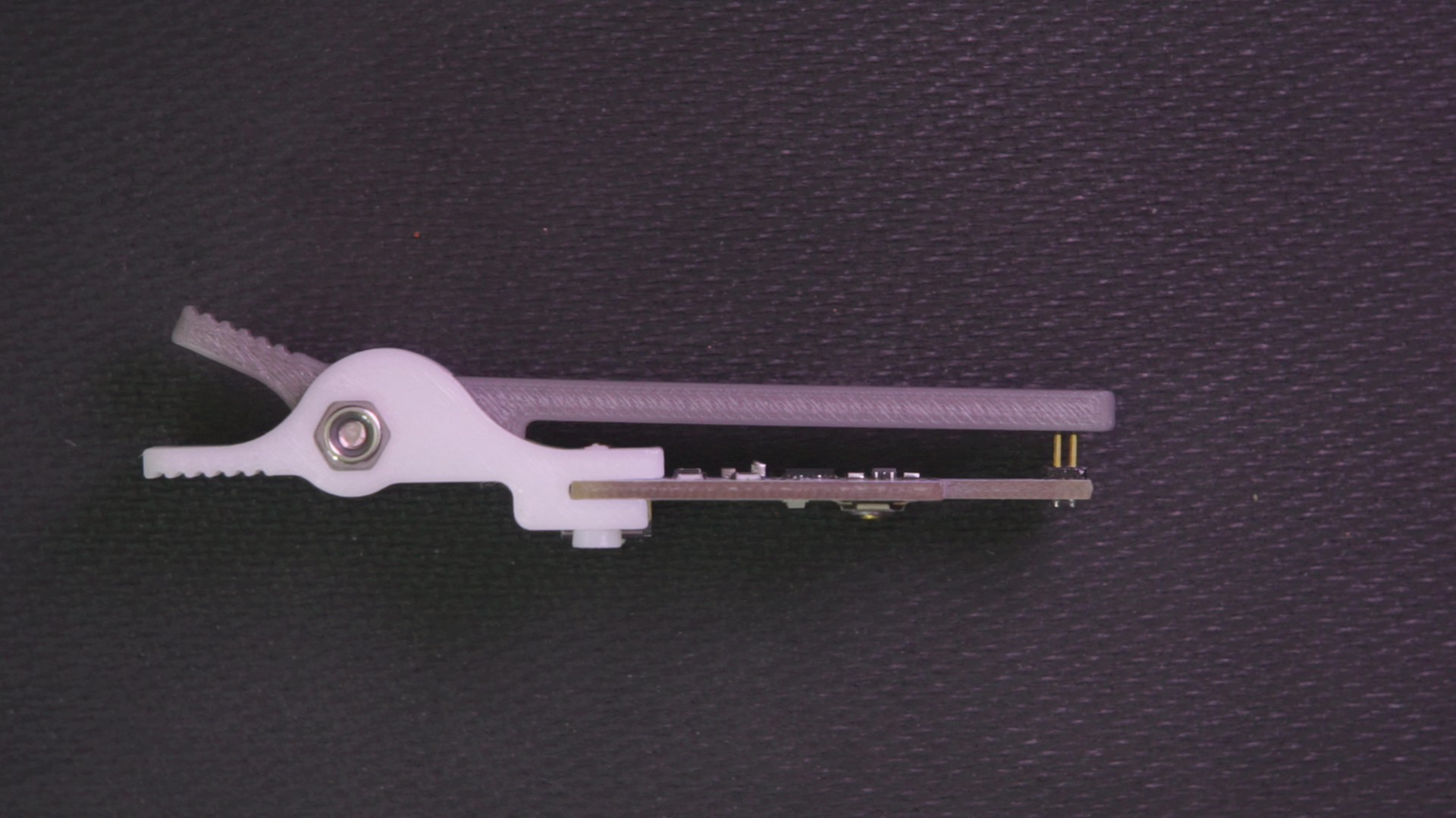
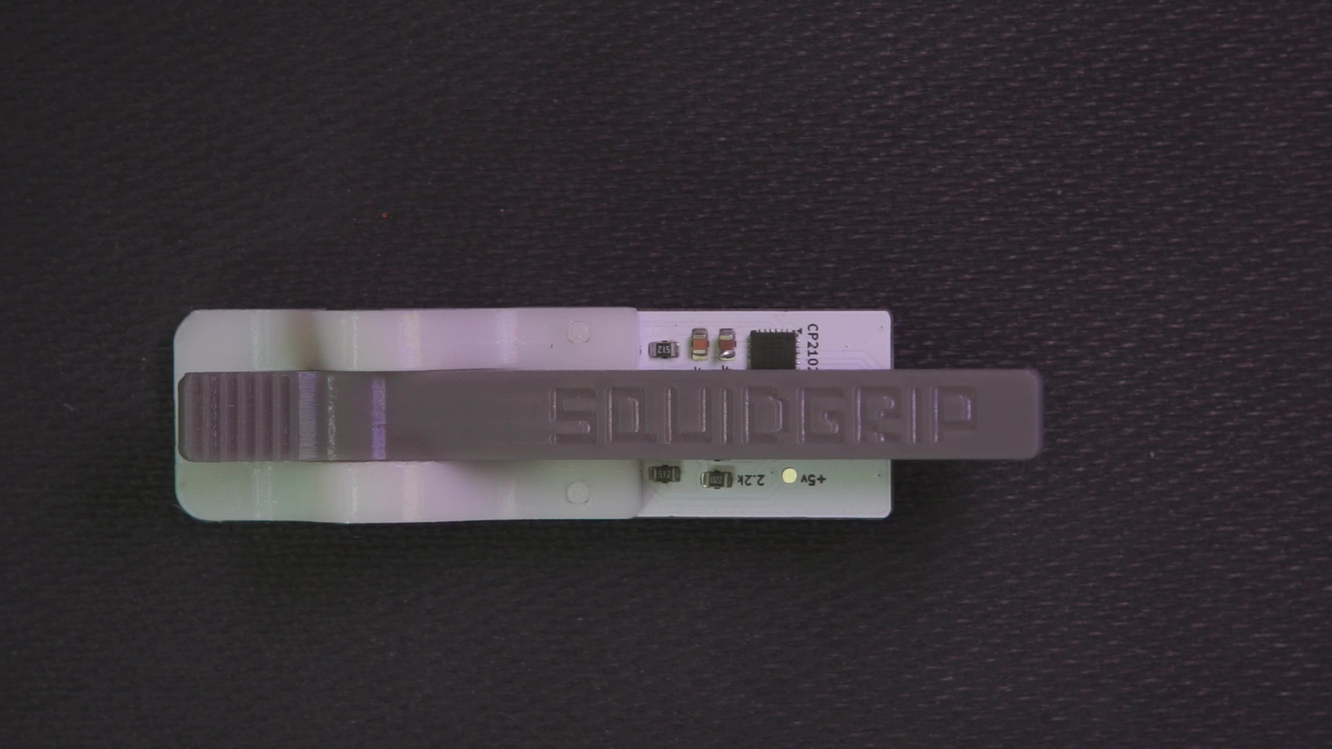
Assembled: front, side and rear
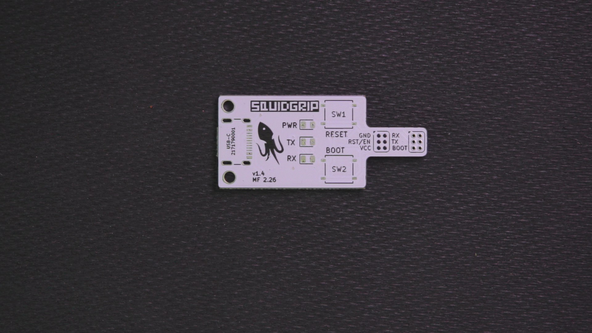
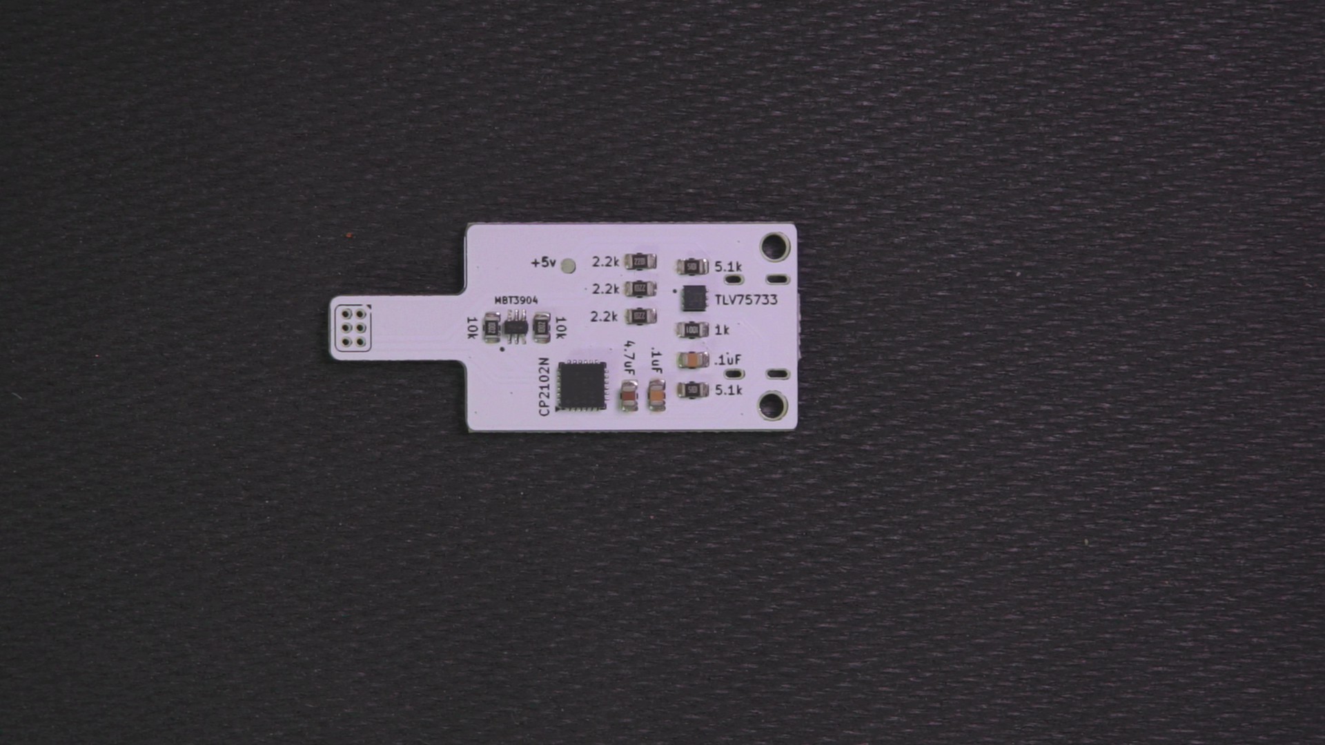
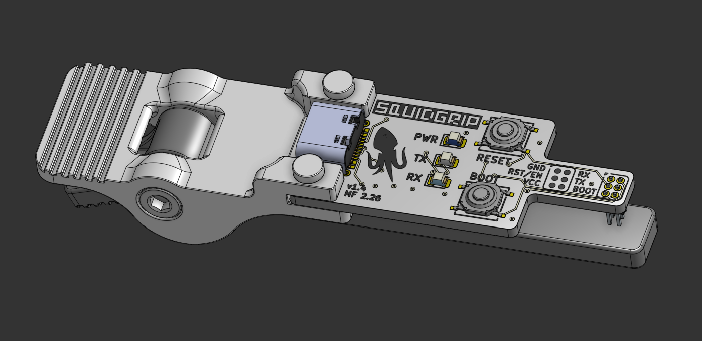
Bare PCB front and rear, and the CAD assembly
firmware/, so a clone comes up with a proper name
instead of as a generic bridge.| Item | Value |
|---|---|
| USB | USB-C receptacle (Molex 2171790001), USB 2.0 only, 5.1 kΩ CC pulldowns |
| USB-UART bridge | Silicon Labs CP2102N-A02-GQFN24 (QFN-24) |
| Regulator | TLV75733, 3.3 V out from USB 5 V |
| Programming pins | 6 pogo pins on a 2x3 array at 1.27 mm pitch (Mill-Max 855-22-006-30-001101) |
| Auto reset | MBT3904DW1T1G dual NPN plus two 10 kΩ resistors, driven by DTR and RTS |
| Buttons | RESET (SW1) and BOOT (SW2), C&K PTS526 SM15 SMTR2 LFS |
| LEDs | PWR (blue), TX (yellow), RX (green) |
| Board | 42.75 x 19.00 mm, 2 layers, 1.51 mm FR-4 core, 1 oz copper, about 1.6 mm total |
| Mounting | 2 x M2 holes plus the 3D printed clamp |
| Clamp parts | clamp_upper.step, clamp_lower.step, pin.step |
   USB-C ─────▶ +5V ─────▶ TLV75733 ─────▶ +3.3V ─────▶ pogo VCC (powers the target)
     │                        (3.3 V LDO)
     │ D+ / D-
     ▼
  CP2102N ── TXD ──▶ pogo RX   (target RXD0)
     │    ── RXD ◀── pogo TX   (target TXD0)
     │
     │ DTR / RTS
     ▼
  MBT3904 (dual NPN) ──▶ pogo RST/EN (target EN) and pogo BOOT (target IO0)

  SW1 = RESET, SW2 = BOOT, D1/D2/D3 = PWR/TX/RX LEDs
The auto-reset part is the standard ESP32 arrangement: DTR and RTS from the CP2102N drive two transistors through 10 kΩ resistors, which pull EN low and hold IO0 low in the right order. That is the same trick an ESP32 dev board uses, so esptool and friends can reset the target into the bootloader by themselves. The buttons do the same job by hand if you need them.
The CP2102N runs off the 3.3 V rail (VREGIN, VDD and VIO are all tied to +3.3 V), senses USB VBUS on +5 V, and has a 1 kΩ pull-up on its reset pin.
Main connections on U1:
| U1 pin | Name | Net |
|---|---|---|
| 3, 4 | D+, D- | USB data from J1 |
| 8 | VBUS | +5V |
| 5, 6, 7 | VIO, VDD, VREGIN | +3.3V |
| 9 | ~RST | R5 1 kΩ pull-up to +3.3V |
| 20, 21 | RXD, TXD | pogo TX (pad 5), pogo RX (pad 6) |
| 19, 23 | ~RTS, ~DTR | auto-reset transistors (U2) |
| 13, 14 | ~TXT, ~RXT | RX and TX LED cathodes |
| 2, 25 | GND | GND |
Six pins, 2x3 array at 1.27 mm pitch. One column is GND / RST-EN / VCC and the other is RX / TX / BOOT, and the silkscreen labels match the layout. TX and RX are named from the target's point of view, so the pin marked RX is the one the probe drives and the pin marked TX is the one the probe reads.
| Silk | Pad | Net | Probe side | Target side |
|---|---|---|---|---|
| GND | 1 | GND | ground | ground |
| RST/EN | 2 | /RESET | auto-reset transistor, SW1 | EN (reset) |
| VCC | 3 | +3.3V | 3.3 V from the LDO | 3V3 |
| BOOT | 4 | /BOOT | auto-reset transistor, SW2 | IO0 (boot select) |
| TX | 5 | /RXD | CP2102N RXD (input) | target TXD0 |
| RX | 6 | /TXD | CP2102N TXD (output) | target RXD0 |
To put it on your own board: 6 pads, 1 mm diameter, 0.54 mm holes, 1.27 mm pitch, in a 2x3 block with
that pinout. It is in this repo as hardware/squidgrip_pogo_2x03_P1.27mm.kicad_mod, and the
SquidTX Nano TX board carries it as SG1, so the two
work together out of the box.
The CP2102N leaves the factory with a generic identity, so it needs a one-time configuration before
the probe behaves like a squidgrip. That configuration is in firmware/, and Silicon Labs' own tool
programs it.
Tool: Simplicity Studio with the
Xpress Configurator. The firmware/ folder is a Simplicity Studio project, and its settings file
pins the exact part (ffd.usbxpress.cp2102n.cp2102n_a02_gqfn24).
| File | What it is |
|---|---|
firmware/.project, firmware/.settings/ | Simplicity Studio project metadata, so the folder opens straight in the IDE |
firmware/squidgrip.document | the device configuration document |
firmware/squidgrip.configuration | the saved configuration: FilterVidPid 10C4:EA60 plus the config byte array |
Steps:
firmware/ project, or make a new Xpress Configurator project and open its document file.squidgrip). The manufacturer string and serial number are also there.The configuration keeps Silicon Labs' VID/PID (10C4:EA60) instead of a custom one, and that is
deliberate: the stock VCP driver matches it, so there are no .inf edits and no driver install. If
you change the VID/PID you are on your own for driver matching.
Two notes from Silicon Labs' documentation. If Simplicity Studio does not pick up the new name after
programming, clear its device cache: delete the device's .info file from
SimplicityStudio/<workspace>/.metadata/.plugins/com.silabs.ss.platform.device.core/device and
replug. And if the product string in squidgrip.configuration is still Silicon Labs' default
(CP2102N USB to UART Bridge Controller), then that is the field to change in step 3.
Plug the squidgrip into USB. The blue PWR LED lights up and a serial port appears. The CP2102N needs no drivers on Windows 10 or newer, macOS and Linux.
Line the tongue up with the pad array on the target board and close the clamp. The pogo pins point down from the underside of the tongue, so the target sits below it.
Flash. The auto-reset circuit does the reset and boot pin dance for you, so anything that talks to a serial port works: the ExpressLRS Configurator (pick the target, set the upload method to UART, choose the COM port, Build & Flash), PlatformIO, the Arduino IDE, or plain esptool, for example:
esptool.py --chip esp32 --port COM5 --baud 921600 write_flash 0x0 firmware.binThe TX and RX LEDs blink with traffic, so you can see whether the target is answering. If a tool cannot get the target into the bootloader, do it by hand: hold BOOT, tap RESET, release BOOT.
Two things worth knowing:
It works like an alligator clip. Three printed parts in hardware/clamp_design/:
| File | Part | Qty |
|---|---|---|
squidgrip - clamp_upper.step | upper jaw (SQUIDGRIP embossed on it) | 1 |
squidgrip - clamp_lower.step | lower jaw | 1 |
squidgrip - pin.step | pins that connect the PCB to the print | 2 |
Hardware:
| Part | McMaster-Carr | Qty |
|---|---|---|
| M3 x 16 mm socket head cap screw | 91292A115 | 1 |
| M3 nyloc nut | 93625A100 | 1 |
| Spring (in the handle) | 9271K577 | 2 |
The two printed pins hold the PCB to the clamp, the M3 screw and nyloc nut are the pivot, and the two
springs sit in the handle so the jaws spring back open. The target board goes between the jaws, under
the tongue. The one in the photos is FDM printed, so print settings are up to you. squidgrip.step
in hardware/manufacturing/ is the finished assembly if you want to check clearances before
printing.
Parts that LCSC can assemble (this is the CSV in hardware/manufacturing/):
| Ref | Value / Part | Package | LCSC |
|---|---|---|---|
| U1 | CP2102N-A02-GQFN24R | QFN-24 4x4 | C969151 |
| U2 | MBT3904DW1T1G | SOT-363 | C110150 |
| U3 | TLV75733PDRVR | WSON-6 2x2 | C2868428 |
| C1 | 4.7 µF | 0805 | C1779 |
| C2, C3 | 0.1 µF | 0805 | C1711 |
| R1, R8 | 10 kΩ | 0805 | C17414 |
| R5 | 1 kΩ | 0805 | C17513 |
| R6, R7 | 5.1 kΩ | 0805 | C27834 |
| R9, R10, R11 | 2.2 kΩ | 0805 | C17520 |
Everything else is hand soldered:
| Ref | Part | Notes |
|---|---|---|
| J1 | Molex 2171790001 | USB-C receptacle |
| SG1 | Mill-Max 855-22-006-30-001101 | 6-position pogo pin header |
| SW1, SW2 | C&K PTS526 SM15 SMTR2 LFS | RESET and BOOT switches |
| D1, D2, D3 | 0805 LEDs, yellow / green / blue | TX, RX, PWR |
| - | 2 x M2 screws | PCB to clamp |
| - | pivot pin or screw for the hinge | see hardware/clamp_design/ |
| File | Description |
|---|---|
hardware/squidgrip.kicad_pro | KiCad project (design rules and netclass) |
hardware/squidgrip.kicad_sch | schematic (title block: Squidgrip ESP32 Interface, rev 1.4, Midnight CAD) |
hardware/squidgrip.kicad_pcb | PCB layout |
hardware/manufacturing/squidgrip-v1.4-gerbers.zip | gerber and drill package, ready to upload |
hardware/manufacturing/gerbers/ | the same files unpacked (F and B Cu, mask, paste, silk, Edge_Cuts, PTH and NPTH drills, job) |
hardware/manufacturing/squidgrip_v1.4_BOM.csv | BOM with LCSC part numbers, in the JLCPCB assembly format |
hardware/manufacturing/squidgrip.step | 3D model of the assembled board |
hardware/clamp_design/ | clamp STEP files |
hardware/squidgrip_pogo_2x03_P1.27mm.kicad_mod | the 6-pin pogo footprint on its own, for your own boards |
docs/ | photos, layer renders and the CAD image used here |
Fab options that match the layout:
.
├── README.md
├── LICENSE                      # CERN-OHL-S-2.0
├── docs/
│   ├── squidgrip.gif                    # 3D render of the assembly
│   ├── squidgrip_assembled_front.jpg    # photo, assembled front
│   ├── squidgrip_assembled_side.jpg     # photo, side view in the clamp
│   ├── squidgrip_assembled_rear.jpg     # photo, assembled rear
│   ├── squidgrip_pcb_front.jpg          # photo, bare PCB front
│   ├── squidgrip_pcb_rear.jpg           # photo, bare PCB rear
│   ├── squidgrip_assembly_cad.png       # CAD view of the assembly
│   ├── squidgrip_copper_front.png       # KiCad render, front copper and silk
│   └── squidgrip_copper_rear.png        # KiCad render, rear copper and silk
├── firmware/
│   ├── squidgrip.configuration          # CP2102N configuration
│   ├── squidgrip.document               # Xpress Configurator device document
│   ├── .project                         # Simplicity Studio project
│   └── .settings/                       # Simplicity Studio tool settings
└── hardware/
    ├── squidgrip.kicad_pro      # KiCad project
    ├── squidgrip.kicad_sch      # schematic
    ├── squidgrip.kicad_pcb      # PCB layout
    ├── squidgrip_pogo_2x03_P1.27mm.kicad_mod   # the 6-pin pogo footprint
├── clamp_design/squidgrip is licensed under the CERN Open Hardware Licence Version 2 - Strongly Reciprocal
(CERN-OHL-S-2.0). The full licence text is in LICENSE.
Copyright (C) 2026 Midnight CAD / SquidTX

This source describes Open Hardware and is licensed under the CERN-OHL-S v2.

You may redistribute and modify this source and make products using it under
the terms of the CERN-OHL-S v2 (https://ohwr.org/cern_ohl_s_v2.txt).

This source is distributed WITHOUT ANY EXPRESS OR IMPLIED WARRANTY, INCLUDING
OF MERCHANTABILITY, SATISFACTORY QUALITY AND FITNESS FOR A PARTICULAR PURPOSE.
Please see the CERN-OHL-S v2 for applicable conditions.

Source location: https://github.com/unixvoid/squidgrip| Qty | Value | Footprint | References |
|---|---|---|---|
| 3 | 2.2k | Resistor_SMD:R_0805_2012Metric | R9, R10, R11 |
| 2 | clipboard:60fcd304-72be-431f-978f-28c27a912257 | , | |
| 2 | .1uF | Capacitor_SMD:C_0805_2012Metric | C2, C3 |
| 2 | 10k | Resistor_SMD:R_0805_2012Metric | R1, R8 |
| 2 | 5.1k | Resistor_SMD:R_0805_2012Metric | R6, R7 |
| 2 | LOGO | LOGO | G***, G*** |
| 2 | PTS526 SM15 SMTR2 LFS | extras-2:GSPTS004901 | SW1, SW2 |
| 1 | 1k | Resistor_SMD:R_0805_2012Metric | R5 |
| 1 | 2171790001 | extras-2:MOLEX_2171790001 | J1 |
| 1 | 4.7uF | Capacitor_SMD:C_0805_2012Metric | C1 |
| 1 | 5v testpoint | TestPoint:TestPoint_Pad_1.0x1.0mm | TP1 |
| 1 | BLUE | LED_SMD:LED_0805_2012Metric | D3 |
| 1 | CP2102N-Axx-xQFN24 | Package_DFN_QFN:QFN-24-1EP_4x4mm_P0.5mm_EP2.6x2.6mm | U1 |
| 1 | GRN | LED_SMD:LED_0805_2012Metric | D2 |
| 1 | MBT3904DW1T1G | extras-2:SOT236 | U2 |
| 1 | SQUIDGRIP | extras-2:Untitled | SG1 |
| 1 | TLV75733PDRVR | extras-2:TLV75733PDRVR | U3 |
| 1 | YLW | LED_SMD:LED_0805_2012Metric | D1 |
The 26 most common of 28 parts.
It measures 42.8 × 19 mm and has 2 copper layers, 1.6 mm thick.
28 parts, built around the MBT3904DW1T1G-HXY. The full list of its parts is on this page, with links to each part's symbol and footprint where PCBKit's library has them.
From the unixvoid/squidgrip repository on GitHub, at the commit this page was made from: the board is hardware/squidgrip.kicad_pcb and its schematic hardware/squidgrip.kicad_sch. PCBKit opens the board in the browser, with nothing to install.
Its repository states no licence, so its author keeps all rights: ask unixvoid before reusing the design.
shorepine/tulipcc
The Tulip Creative Computer and AMYboard - portable Python synthesizers

ansemjo/chronovfd
hardware project for a clock around a russian ivl2-5/7 vfd and an esp32-wroom module

haydenridd/silvia-pid-board
The following outlines: - Board circuit design - Hookup/wiring guide - Board mounting - BOM/Fabrication info


HomeOnDuna/Nyx-Flight-Computers
Contains the Nyx flight computer family developed for UNSW Rocketry Avionics team.

mattinglot/dog-collar-light
This is the LED dog collar light PCB and firmware that I built for my dog Joey and a few of his friends.

Mutzi1211/Wasserrakete
Ein Überblick über alle Projektbestandteile – von CAD über Code bis zu Anforderungen und Abgaben.
