

4 layers101.5 × 43.6 mm
Alcantara v.1.0
zenitheesc/Alcantara
Mobile Ground Station for stratospheric probe monitoring and rescue. Goes well with the Zenith Monitor app.
90 parts5

 DerekParks/FTDI_ESP_Programmer
FTDI Breakout with Auto reset for ESP chips
ESP Programmer is an open-source printed circuit board by DerekParks, from the DerekParks/FTDI_ESP_Programmer repository on GitHub. It is a 2-layer board of 42.2 × 28.7 mm with 28 parts on 31 nets, routed with 282 tracks and 27 vias.
It is built around the FT232RL-REEL and MBT3904DW1T1G-HXY. Its parts include 7 capacitors, 6 resistors, 4 connectors, 2 diodes and 2 switches. It belongs with the interfaces and adapters boards of this library.
Around 2008-ish Sparkfun started selling their FTDI basic breakout. These were great! And really helped me move beyond having a full Arduino Uno inside of every project.
Fast forward to today. ESP's are king! But we are in a similar situation where most dev boards include a built in USB-to-TTL chip. At least now, we are using FTDI clones that are cheaper. But I still don't want to include extra hardware just for programming in every project!
For years I have used the 3.3v version of Sparkfun's FTDI breakout for programming ESP's. And for an equal amount of years, I've been annoyed that auto-reset doesn't work like on the all-in-one dev boards.
I will freely admit that support for OTA updates has made this less of an annoyance. But when I am working out bugs, I find iterating with a physical programmer faster.
So at some point during the pandemic, I setout to figure out how the auto-reset feature on ESP's works and to make my own FTDI programmer.
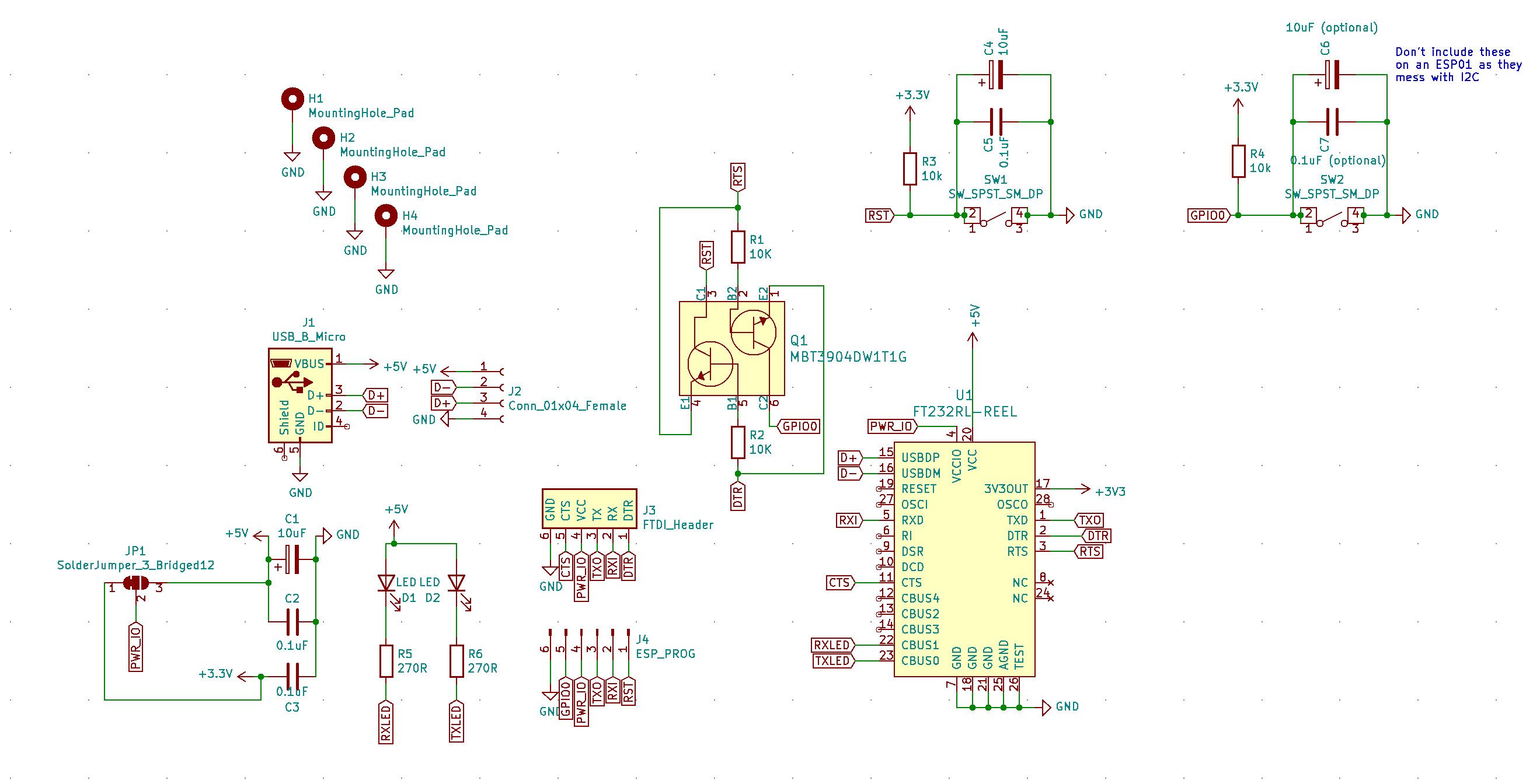
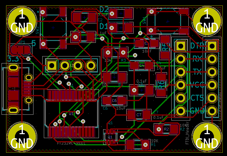
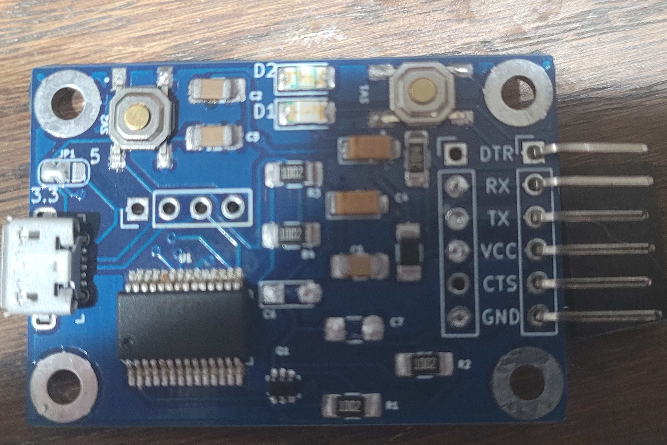 ("V1 where I forgot to add current limiting resistors to the status LED's, D'oh!")
There are also physical tactical flash and reset buttons in case for some reason my amazing auto-reset circuit fails.
Do I even need to link the standards xkcd? Yes, I am proposing a new standard pinout.
| Old Pinouts | My Pinout |
|---|---|
| DTR | RST |
| RX | RX |
| TX | TX |
| VCC | VCC |
| CTS | GPIO0 |
| GND | GND |
As you can see I've replaced DTR and CTS with RST and GPIO0, respectively. This board does have the original FTDI standard pins broken out, just-in-case, but so far I haven't ever had cause to use them.
There is a solder jumper on the board to switch between 3.3v and 5v. It is set to 3.3v by default.
The decoupling, C6 & C7 should be removed if using an ESP01 and I2C.
| Qty | Value | Footprint | References |
|---|---|---|---|
| 4 | 0.1uF | Capacitor_SMD:C_1206_3216Metric_Pad1.42x1.75mm_HandSolder | C2, C3, C5, C7 |
| 4 | MountingHole_Pad | MountingHole:MountingHole_2.7mm_M2.5_Pad | H1, H2, H3, H4 |
| 3 | 10uF | Capacitor_Tantalum_SMD:CP_EIA-3216-18_Kemet-A_Pad1.58x1.35mm_HandSolder | C1, C4, C6 |
| 2 | 10K | Resistor_SMD:R_1206_3216Metric_Pad1.42x1.75mm_HandSolder | R1, R2 |
| 2 | 10k | Resistor_SMD:R_1206_3216Metric_Pad1.42x1.75mm_HandSolder | R3, R4 |
| 2 | 270 | Resistor_SMD:R_1206_3216Metric_Pad1.30x1.75mm_HandSolder | R5, R6 |
| 2 | LED | LED_SMD:LED_1206_3216Metric_Pad1.42x1.75mm_HandSolder | D1, D2 |
| 2 | SW_SPST_SM_DP | ESP_Programmer:E-Switch-TL3342F160QG-0 | SW1, SW2 |
| 1 | Conn_01x04_Female | Connector_PinHeader_2.54mm:PinHeader_1x04_P2.54mm_Vertical | J2 |
| 1 | ESP_PROG | Connector_PinHeader_2.54mm:PinHeader_1x06_P2.54mm_Vertical | J4 |
| 1 | FT232RL-REEL | digikey-footprints:SSOP-28_W5.30mm | U1 |
| 1 | FTDI_Header | avr-arduino:FTDI_Header | J3 |
| 1 | MBT3904DW1T1G | digikey-footprints:SOT-363 | Q1 |
| 1 | SolderJumper_3_Bridged12 | Jumper:SolderJumper-3_P1.3mm_Bridged12_RoundedPad1.0x1.5mm_NumberLabels | JP1 |
| 1 | USB_B_Micro | digikey-footprints:USB_Micro_AB_Female_0475890001 | J1 |
It measures 42.2 × 28.7 mm and has 2 copper layers, 1.6 mm thick.
28 parts, built around the FT232RL-REEL and MBT3904DW1T1G-HXY. The full list of its parts is on this page, with links to each part's symbol and footprint where PCBKit's library has them.
From the DerekParks/FTDI_ESP_Programmer repository on GitHub, at the commit this page was made from: the board is ESP_Programmer.kicad_pcb. PCBKit opens the board in the browser, with nothing to install.
Its repository states no licence, so its author keeps all rights: ask DerekParks before reusing the design.
zenitheesc/Alcantara
Mobile Ground Station for stratospheric probe monitoring and rescue. Goes well with the Zenith Monitor app.

Reid-n0rc/LMS-6_Interface_Board
Interface to the LMS-6 radiosonde carde edge connector.


harp-tech/device.stepperdriver
A stepper motor controller device for four motors including individual quadrature encoders.


