2 layers99.3 × 98.6 mm
FlexiblePS
profdc9/FlexibleCharger
An Arduino-controlled charger for different kinds of batteries, or it can be a standalone power supply
118 parts13
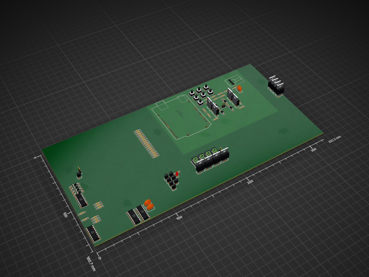
 UNIT-MOS/PCB-Etching-Unit
The board etching unit (BEU) aids in the etching of PCB's with ferric chloride (Fe3Cl).
PCB Etching Unit is an open-source printed circuit board by UNIT-MOS, from the UNIT-MOS/PCB-Etching-Unit repository on GitHub. It is a 2-layer board with 92 parts on 98 nets, routed with 215 tracks and 4 vias.
It is built around the HDSP-7801, TIP42 and BC558, with the TIP41 among its other parts. Its parts include 40 resistors, 20 transistors, 9 diodes, 8 ICs and 7 switches. It belongs with the AVR (ATmega, ATtiny) boards of this library.


The BEU assists in the etching of PCB'S using FeCl3, so the operator gets to do more interesting things in the meantime. BEU aims to achieve the following goals
Two DC motors will move the FeCl3 container directly by connecting to drilled holes.
A 3D-printed support beam will hold the motors at a sufficient height.
Desired dimensions can be configured in the OpenScad-file.
This should enable the operator to choose a container of arbitrary width or length. If a chosen container
is small enough to be held by one motor, a single support beam with a counterweight can be used.
In the spirit of this project, the board will be etched by the operator.
The operator can read up on the procedure here, it's the best primer for selfmade PCB's we've found so far.
Used my dormant Arduino Uno board for revision 0. A dev board for 20€ is fine for revision 0 but it did screw over the goal of low material cost.
Following revisions might use a PIC, the instruction set seems compact enough for some assembly and I found several primers covering them (IDE: PIKDEV).
Though the AVR software will be done in C for now.
Since I'm using a plastic container, I skipped on heating the FeCl3 this time. Aluminium seems to be easy to solder/weld, might be used for later revisions.
Closed loop temperature controll could be done using a PT100 or Typ K element, if the casing survives extended exposure to FeCl3.
The board just etches on one side, with the other one facing down. A support beam could hold it up, but the support itself would cover parts of the board too.
Vertical support on the left and right with 1 mm width could work.
| Qty | Value | Footprint | References |
|---|---|---|---|
| 21 | 1K | Resistor_THT:R_Axial_DIN0204_L3.6mm_D1.6mm_P7.62mm_Horizontal | R1, R2, R10, R12, R13, R16, R18, R19, R20, R21, R23, R25, R26, R30, R32, R34 +5 |
| 8 | 1N4001 | Diode_THT:D_DO-41_SOD81_P10.16mm_Horizontal | D1, D2, D3, D4, D5, D6, D7, D8 |
| 8 | TIP42 | Package_TO_SOT_THT:TO-220-3_Vertical | Q1, Q2, Q3, Q4, Q5, Q8, Q10, Q13 |
| 7 | 2.2K | Resistor_THT:R_Axial_DIN0204_L3.6mm_D1.6mm_P7.62mm_Horizontal | R3, R6, R8, R11, R31, R33, R35 |
| 7 | BC558 | Package_TO_SOT_THT:TO-92_Inline | Q14, Q15, Q16, Q17, Q18, Q19, Q20 |
| 7 | SW_MEC_5G | Button_Switch_THT:SW_TH_Tactile_Omron_B3F-106x | SW1, SW2, SW3, SW4, SW5, SW6, SW7 |
| 4 | 5.6K | Resistor_THT:R_Axial_DIN0204_L3.6mm_D1.6mm_P7.62mm_Horizontal | R15, R17, R22, R24 |
| 4 | HDSP-7801 | Display_7Segment:HDSP-7801 | U1, U2, U3, U4 |
| 4 | TIP41 | Package_TO_SOT_THT:TO-220-3_Vertical | Q6, Q7, Q9, Q11 |
| 3 | 100nF | Capacitor_THT:C_Disc_D9.0mm_W5.0mm_P5.00mm | C1, C2, C3 |
| 2 | 330R | Resistor_THT:R_Axial_DIN0204_L3.6mm_D1.6mm_P7.62mm_Horizontal | R28, R40 |
| 2 | 4027 | Package_DIP:DIP-16_W7.62mm | U5, U6 |
| 2 | Motor_DC | Connector_PinHeader_2.54mm:PinHeader_1x02_P2.54mm_Vertical | M1, M2 |
| 1 | 15K | Resistor_THT:R_Axial_DIN0204_L3.6mm_D1.6mm_P7.62mm_Horizontal | R38 |
| 1 | 2K | Resistor_THT:R_Axial_DIN0204_L3.6mm_D1.6mm_P7.62mm_Horizontal | R27 |
| 1 | 2N3904 | Package_TO_SOT_THT:TO-92_Inline | Q12 |
| 1 | 3.3K | Resistor_THT:R_Axial_DIN0204_L3.6mm_D1.6mm_P7.62mm_Horizontal | R14 |
| 1 | 4011 | Package_DIP:DIP-14_W7.62mm | U9 |
| 1 | 4511 | Package_DIP:DIP-16_W7.62mm | U11 |
| 1 | 470K | Resistor_THT:R_Axial_DIN0204_L3.6mm_D1.6mm_P7.62mm_Horizontal | R39 |
| 1 | 5K | Potentiometer_THT:Potentiometer_Piher_T-16H_Single_Horizontal | RV1 |
| 1 | 6.8K | Resistor_THT:R_Axial_DIN0204_L3.6mm_D1.6mm_P7.62mm_Horizontal | R37 |
| 1 | 620R | Resistor_THT:R_Axial_DIN0204_L3.6mm_D1.6mm_P7.62mm_Horizontal | R29 |
| 1 | Arduino_UNO_R2 | Module:Arduino_UNO_R2_WithMountingHoles | A1 |
| 1 | Buzzer | Connector_PinHeader_2.54mm:PinHeader_1x02_P2.54mm_Vertical | BZ1 |
| 1 | LED | LED_THT:LED_D3.0mm | D9 |
92 parts, built around the HDSP-7801, TIP42, BC558 and TIP41. The full list of its parts is on this page, with links to each part's symbol and footprint where PCBKit's library has them.
From the UNIT-MOS/PCB-Etching-Unit repository on GitHub, at the commit this page was made from: the board is PCB_Etching_Unit/PCB_Etching_Unit.kicad_pcb and its schematic PCB_Etching_Unit/PCB_Etching_Unit.kicad_sch. PCBKit opens the board in the browser, with nothing to install.
Its repository states no licence, so its author keeps all rights: ask UNIT-MOS before reusing the design.
profdc9/FlexibleCharger
An Arduino-controlled charger for different kinds of batteries, or it can be a standalone power supply

promesoft/KicadJE-EuroPowerSupply
Takes a Laptop 19V input and makes +-12 and 5 v out

Markus-Fitz/Protection-board
Speaker-protection board for power amplifier.

MUDAL/Function-Generator
Custom Function Generator designed and developed by Olaoluwa Raji. This project is a complete embedded system solution with both hardware and software implemented by me. Relevant reference materials are included.


ANSHAD134/PCB-Files
A collection of my personal KiCad PCB design projects, custom symbol/footprint libraries, and 3D models used across different electronics builds.

