Skip to the content
PCBKitNew board
2 layers99.3 × 98.6 mmFlexiblePS, the printed circuit board in 3D

An Arduino-controlled charger for different kinds of batteries, or it can be a standalone power supply

Size
99.3 × 98.6 mm
Copper layers
2
Thickness
1.6 mm
Parts
118
Nets
76
Pads
320
Tracks, vias
932, 12
Pours
8
Routed
Yes
KiCad
KiCad 4
Created
9 Mar 2021
Updated
14 Feb 2023

Overview

FlexiblePS is an open-source printed circuit board by profdc9, from the profdc9/FlexibleCharger repository on GitHub. It is a 2-layer board of 99.3 × 98.6 mm with 118 parts on 76 nets, routed with 932 tracks and 12 vias.

It is built around the ATMEGA328P-PU, LM358 and TL494, with the SB580, TIP41 and TIP41C among its other parts. Its parts include 50 resistors, 31 capacitors, 15 connectors, 7 ICs and 7 diodes. It belongs with the power boards and the AVR (ATmega, ATtiny) boards of this library.

Main components

7

README

README.md

FlexibleCharger

This is a battery charger based on a commonly-available ATMEGA328P for control and a common TL494 switching power supply IC. It is intended to be easily and cheaply reproduced, and is for experimentation with different methods of charging batteries. It is also useful as a power supply.

It is licensed under the Creative Commons CC-BY-SA 4.0, attribution and share-alike clauses. It is open-source hardware and software created by Daniel Marks. The schematic, gerber files, and Arduino code is available under open source licenses.

The device is intended to be powered from another unregulated or switching power supply, with up to 30 volts input. As given in the schematic, the output can be up to 24 volts and 6 amps. It would be possible to modify the circuit to perhaps allow for up to 28 volts and 15 amps.

It is designed to be used independently of a computer, having a simple user interface of three buttons and a 2-by-16 LCD alphanumeric display. The software has been created in the Arduino environment to be easily modified and customized.

WARNING: Since this device gives you the ability to specify the voltage and/or current you wish to charge with, it is easily possible to damage or blow up batteries with improper configuration. This is especially true of lithium batteries which can catch fire and be difficult to extinguish. The author is not responsible for damage or injury resulting from the use of the device, as it is intended for experimentation.

The device must be calibrated before used, with the calibration parameters stored in EEPROM. To do this, you need a voltmeter, a calibrated resistor with a known resistance from 5 to 10 ohms, and a wire to use as a short circuit load. The procedure is:

  • Choose the "Calibrate" menu options from the main menu.
  • Remove any load from the output so that the output is open circuit.
  • Press the button and the charger will apply a test voltage to the output terminals.
  • Use a voltmeter to measure this voltage and enter it into the charger.
  • Connect the calibrated resistor to output.
  • Enter the resistance in ohms of the calibrated resistor.
  • Press the button and the charger will apply a constant current to the charger terminals.
  • Measure the voltage at the terminals of the calibrated resistor at the output.
  • Press the button to end applying the current so that the resistor does not get too hot.
  • Enter the measured voltage across the resistor terminals.
  • Place the shorting wire across the output terminals.
  • Press the button and the charger will apply a constant current to the charger terminals.
  • After a few seconds, the charger shuts off the current and the calibration is complete.

To charge a battery, one must first enter a charging program. At the time of this writing, there only two types of charging programs: Constant Voltage/Constant Current and Pulsed Recovery mode. The "Change Program" is used to select the type of program and the parameters for the program. There are 12 program banks currently.

  • Constant Voltage/Constant Current: Charge with a maximum constant current until a particular voltage is reached, then hold the voltage constant. This may be used, for example, to float batteries. The combination of constant voltage and constant current limits the power delivered to the battery.

  • Pulsed Recovery Mode: This is intended to be a mode that desulfates lead-acid cells. It has multiple parameters. Pulsed Voltage/Pulsed Current are the maximum voltage and current to apply during a pulse. Pulse length is the duration of the current pulse to apply to the battery. Interval is the time between pulses, which should be much longer than the pulse length so that significant heat does not build up in the battery. Recovery volts is the voltage that the charger checks for when no current is applied to see if the battery has become sufficiently desulfated for normal charging. Target volts and trickle charge is the maximum voltage and current to apply when charging after the recovery voltage has been achieved to trickle charge the battery to capacity.

"Execute Program" is used to start a charging program. The charging programs generally may be aborted by pressing the rightmost button.

"Power supply" is a mode that may be used to use the charger like a constant voltage/constant current power supply. The current limit is approximate and is intended to prevent short circuits from causing device damage.

Please take care when using this device, as it can potentially cause batteries to burn or explode. Do not leave batteries unattended when charging.
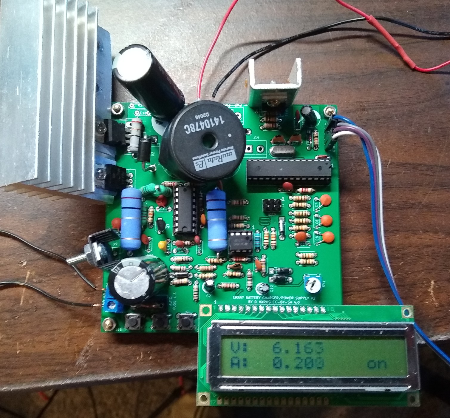
PCB

Parts

118
QtyValueFootprintReferences
2110kResistors_THT:R_Axial_DIN0207_L6.3mm_D2.5mm_P7.62mm_HorizontalR1, R2, R15, R18, R21, R22, R24, R28, R29, R30, R36, R40, R43, R45, R46, R48 +5
13100nFCapacitors_THT:C_Disc_D5.0mm_W2.5mm_P5.00mmC1, C5, C6, C7, C9, C11, C16, C23, C24, C25, C26, C34, C35
81kResistors_THT:R_Axial_DIN0207_L6.3mm_D2.5mm_P7.62mm_HorizontalR5, R25, R26, R27, R32, R37, R47, R49
5100kResistors_THT:R_Axial_DIN0207_L6.3mm_D2.5mm_P7.62mm_HorizontalR4, R10, R11, R16, R44
5Conn_01x02Buttons_Switches_THT:SW_PUSH_6mm_h4.3mmJ4, J8, J9, J13, J15
41N5819Diodes_THT:D_DO-41_SOD81_P7.62mm_HorizontalD1, D3, D5, D8
4Conn_01x01Connectors:1pinJ6, J7, J10, J11
4Conn_01x02Connectors_Terminal_Blocks:TerminalBlock_bornier-2_P5.08mmJ1, J3, J5, J14
31MResistors_THT:R_Axial_DIN0207_L6.3mm_D2.5mm_P7.62mm_HorizontalR3, R13, R20
20R1Resistors_THT:R_Axial_DIN0414_L11.9mm_D4.5mm_P20.32mm_HorizontalR14, R34
210 nFCapacitors_THT:C_Disc_D5.0mm_W2.5mm_P5.00mmC4, C14
210 uFCapacitors_THT:CP_Radial_D5.0mm_P2.50mmC2, C12
2100 nFCapacitors_THT:C_Disc_D5.0mm_W2.5mm_P5.00mmC21, C37
21000 pFCapacitors_THT:C_Disc_D5.0mm_W2.5mm_P5.00mmC10, C22
21000 uFCapacitors_THT:CP_Radial_D14.0mm_P7.50mmC13, C15
222pFCapacitors_THT:C_Disc_D5.0mm_W2.5mm_P5.00mmC19, C30
22k2Resistors_THT:R_Axial_DIN0207_L6.3mm_D2.5mm_P7.62mm_HorizontalR23, R33
2LMT85TO_SOT_Packages_THT:TO-92_Inline_WideU5, U6
11 nFCapacitors_THT:C_Disc_D5.0mm_W2.5mm_P5.00mmC3
110 uFCapacitors_THT:C_Disc_D5.0mm_W2.5mm_P5.00mmC8
1100RResistors_THT:R_Axial_DIN0414_L11.9mm_D4.5mm_P20.32mm_HorizontalR31
1100RResistors_THT:R_Axial_DIN0309_L9.0mm_D3.2mm_P12.70mm_HorizontalR17
1100uFCapacitors_THT:CP_Radial_D8.0mm_P3.50mmC32
1150 uHInductors_THT:L_Radial_D18.0mm_P10.00mmL1
116MHzCrystals:Crystal_HC49-U_VerticalX3
11N4007Diodes_THT:D_DO-41_SOD81_P7.62mm_HorizontalD11
11N4148Diodes_THT:D_DO-35_SOD27_P7.62mm_HorizontalD19
11k8Resistors_THT:R_Axial_DIN0207_L6.3mm_D2.5mm_P7.62mm_HorizontalR42
122 pFCapacitors_THT:C_Disc_D5.0mm_W2.5mm_P5.00mmC20
1220RResistors_THT:R_Axial_DIN0309_L9.0mm_D3.2mm_P12.70mm_HorizontalR19
1220RResistors_THT:R_Axial_DIN0207_L6.3mm_D2.5mm_P7.62mm_HorizontalR12
12N3906TO_SOT_Packages_THT:TO-92_Inline_WideQ3
133RResistors_THT:R_Axial_DIN0309_L9.0mm_D3.2mm_P12.70mm_HorizontalR35
14k7Resistors_THT:R_Axial_DIN0207_L6.3mm_D2.5mm_P7.62mm_HorizontalR38
156 pFCapacitors_THT:C_Disc_D5.0mm_W2.5mm_P5.00mmC17
1620kResistors_THT:R_Axial_DIN0207_L6.3mm_D2.5mm_P7.62mm_HorizontalR41
1ATMEGA328P-PUHousings_DIP:DIP-28_W7.62mm_SocketU1
1Conn_01x04Pin_Headers:Pin_Header_Straight_1x04_Pitch2.54mmJ12
1Conn_02x03_Odd_EvenPin_Headers:Pin_Header_Straight_2x03_Pitch2.54mmJ2
1LCD-016N002LPin_Headers:Pin_Header_Straight_1x16_Pitch2.54mmU3
1LM358Housings_DIP:DIP-8_W7.62mm_SocketU2
1LM7805_TO220TO_SOT_Packages_THT:TO-220-3_VerticalU9
1NCResistors_THT:R_Axial_DIN0207_L6.3mm_D2.5mm_P7.62mm_HorizontalR39
1NCCapacitors_THT:C_Disc_D5.0mm_W2.5mm_P5.00mmC18
1POTPotentiometers:Potentiometer_Triwood_RM-065RV1
1SB580Diodes_THT:D_DO-201_P12.70mm_HorizontalD2
1SL-506PFlexiblePS:SL506PfuseholderF1
1TIP41FlexiblePS:TO-247_TO-3P_VerticalQ2
1TIP41CTO_SOT_Packages_THT:TO-220-3_VerticalQ4
1TIP42TO_SOT_Packages_THT:TO-220-3_VerticalQ1
1TL494Housings_DIP:DIP-16_W7.62mm_SocketU4

Questions

How big is the FlexiblePS PCB?

It measures 99.3 × 98.6 mm and has 2 copper layers, 1.6 mm thick.

What parts does the FlexiblePS use?

118 parts, built around the ATMEGA328P-PU, LM358, TL494 and SB580. The full list of its parts is on this page, with links to each part's symbol and footprint where PCBKit's library has them.

Where can I download the FlexiblePS KiCad files?

From the profdc9/FlexibleCharger repository on GitHub, at the commit this page was made from: the board is FlexiblePS/FlexiblePS.kicad_pcb. PCBKit opens the board in the browser, with nothing to install.

Can I use the FlexiblePS design in my own project?

Its repository states no licence, so its author keeps all rights: ask profdc9 before reusing the design.

Similar boards

  • 2 layers65 × 85 mmFunction Generator, the printed circuit board in 3D

    Function Generator

    MUDAL/Function-Generator

    Custom Function Generator designed and developed by Olaoluwa Raji. This project is a complete embedded system solution with both hardware and software implemented by me. Relevant reference materials are included.

    30 parts1GPL-3.0
  • 2 layers147.3 × 91.4 mmSchematic initialization, the printed circuit board in 3D

    Schematic initialization

    smitshah/Laptop-Charger

    The Gerber files of PCB are in .pdf and .gbr format.

    39 partsGPL-3.0
  • 2 layers162.6 × 86.4 mmBms, the printed circuit board in 3D

    Bms

    akbar-q/Circuits-PCB-HardwareDesign

    The High Voltage Arc Detector is a non-contact RF-based sensing system that detects high-voltage electrical arcs.

    53 parts
  • 2 layers100 × 100 mmKicadJE EuroPowerSupply, the printed circuit board in 3D

    KicadJE EuroPowerSupply

    promesoft/KicadJE-EuroPowerSupply

    Takes a Laptop 19V input and makes +-12 and 5 v out

    107 parts8MIT
  • 2 layers77.5 × 50.8 mmProtection board, the printed circuit board in 3D

    Protection board

    Markus-Fitz/Protection-board

    Speaker-protection board for power amplifier.

    71 parts1GPL-3.0
  • 2 layers211.2 × 87.8 mmOriginal, the printed circuit board in 3D

    Original

    Ajay-Mallesh/PCB-Designs

    Collection of PCB designs -> Basic circuits

    71 parts
  • 2 layers55.7 × 48.7 mmAmplifier, the printed circuit board in 3D

    Amplifier

    ANSHAD134/PCB-Files

    A collection of my personal KiCad PCB design projects, custom symbol/footprint libraries, and 3D models used across different electronics builds.

    20 parts
  • 2 layers158 × 64 mmRegulator, the printed circuit board in 3D

    Regulator

    gx1400/KiCad_PowerSupply_RegulatorAndControl

    91 parts