4 layers17.8 × 68.6 mm

 ulyssecrn/usb-pd-card
PCB business card: USB-C PD charger tester + battery-free NFC tag.
Usb pd card is an open-source printed circuit board by ulyssecrn, from the ulyssecrn/usb-pd-card repository on GitHub. It is a 2-layer board of 85.6 × 54 mm with 50 parts on 53 nets, routed with 173 tracks and 23 vias.
It is built around the CH32X035G8U6, ME6228A33M3G and NT3H2111W0FHKH, with the H7VL10B and SMF20A among its other parts. Its parts include 18 resistors, 16 diodes, 5 capacitors, 3 ICs and 1 connector. It belongs with the power and radio and wireless boards of this library.


A credit-card-sized PCB business card that is also a USB-C PD charger tester and a battery-free NFC tag.
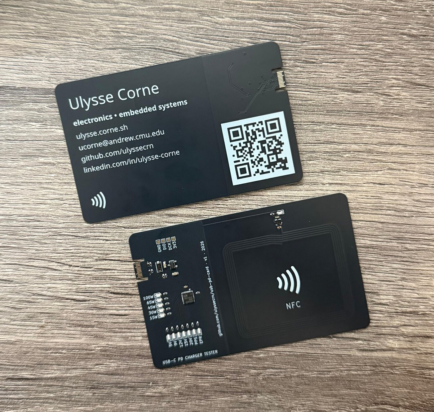
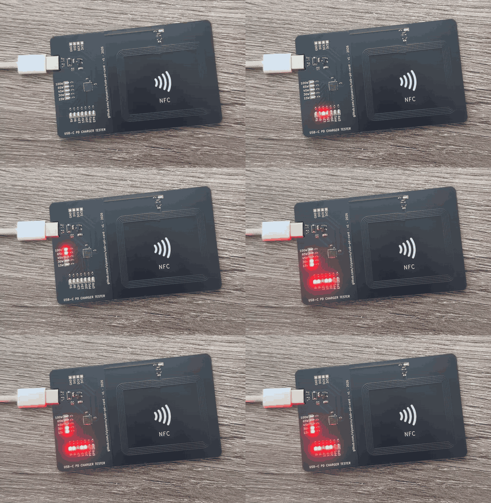
| Board | 85.6 × 54 mm (ID-1), 0.6 mm FR4, 2 layers, ENIG, matte black mask |
| USB-C | PCB-edge paddle, tongue cut into the board; CC1/CC2 with 5.1 kΩ Rd + ESD |
| MCU | WCH CH32X035G8U6 (RISC-V, built-in USB PD PHY) |
| Power | ME6228 3.3 V LDO from VBUS, SMF20A TVS |
| NFC | NXP NT3H2111 + on-board 5-turn coil (≈ 2.3 µH estimated) |
| Assembly | JLCPCB PCBA, all parts on the front |
usb-pd-card.kicad_*: KiCad 10 project (schematic + PCB)lib/: project symbols and footprints (USB-C paddle derived from flip-card, MIT)lib/nfc-coils.pretty/: generated NFC coil footprintstools/nfc_coil.py: coil generator and inductance estimator (plain Python, no dependencies). Try python3 tools/nfc_coil.py selftest.firmware/: CH32X035 firmware (ch32fun, nix-shell, flashed with an RP2040 programmer). See firmware/README.md.jlcpcb/: v1 production files (Gerbers, BOM, CPL)AGENTS.md: full design notes, pin map and decisionsAGENTS.md).| Qty | Value | Footprint | References |
|---|---|---|---|
| 13 | LED | LED_SMD:LED_0603_1608Metric | D2, D5, D6, D7, D8, D9, D10, D11, D12, D13, D14, D15, D16 |
| 12 | 1k | Resistor_SMD:R_0402_1005Metric | R7, R8, R9, R10, R11, R12, R13, R14, R15, R16, R17, R18 |
| 2 | 10uF | Capacitor_SMD:C_0603_1608Metric | C2, C4 |
| 2 | 5.1k | Resistor_SMD:R_0402_1005Metric | R2, R3 |
| 2 | H7VL10B | Diode_SMD:D_0402_1005Metric | D3, D4 |
| 1 | 100k | Resistor_SMD:R_0402_1005Metric | R4 |
| 1 | 100nF | Capacitor_SMD:C_0402_1005Metric | C5 |
| 1 | 10k | Resistor_SMD:R_0402_1005Metric | R6 |
| 1 | 15k | Resistor_SMD:R_0402_1005Metric | R5 |
| 1 | 2.75uH | nfc-coils:NFC_Coil_Rect_38x46mm_R4_5T_W0.5_S0.3 | L1 |
| 1 | 220nF | Capacitor_SMD:C_0402_1005Metric | C1 |
| 1 | 47 | Resistor_SMD:R_0402_1005Metric | R1 |
| 1 | CH32X035G8U6 | Package_DFN_QFN:WQFN-28-1EP_4x4mm_P0.4mm_EP2.7x2.7mm | U1 |
| 1 | GND | TestPoint:TestPoint_Pad_1.0x1.0mm | TP4 |
| 1 | LOGO | koda:tapsmall | G*** |
| 1 | LOGO | koda:nfctap | G*** |
| 1 | ME6228A33M3G | business-card:SOT-23-3_L2.9-W1.6-P1.90-LS2.8-BR | U2 |
| 1 | NT3H2111W0FHKH | business-card:XQFN-8_L1.6-W1.6-P0.50-BL_NT3H2111W0FHKH | U3 |
| 1 | SMF20A | Diode_SMD:D_SOD-123F | D1 |
| 1 | SWCLK | TestPoint:TestPoint_Pad_1.0x1.0mm | TP2 |
| 1 | SWIO | TestPoint:TestPoint_Pad_1.0x1.0mm | TP1 |
| 1 | USB_C_Receptacle_USB2.0_14P | business-card:USB_C_Paddle | J1 |
| 1 | VDD | TestPoint:TestPoint_Pad_1.0x1.0mm | TP3 |
| 1 | tune | Capacitor_SMD:C_0402_1005Metric | C3 |
It measures 85.6 × 54 mm and has 2 copper layers, 0.6 mm thick.
50 parts, built around the CH32X035G8U6, ME6228A33M3G, NT3H2111W0FHKH and H7VL10B. The full list of its parts is on this page, with links to each part's symbol and footprint where PCBKit's library has them.
From the ulyssecrn/usb-pd-card repository on GitHub, at the commit this page was made from: the board is usb-pd-card.kicad_pcb and its schematic usb-pd-card.kicad_sch. PCBKit opens the board in the browser, with nothing to install.
Its repository states no licence, so its author keeps all rights: ask ulyssecrn before reusing the design.


nanographs/Open-Beam-Interface
Just what you need to control the beam and get an image.

OpenLogicEFI/Hardware
Hardware is based off an open source project called Speeduino by Josh Stewart.

blonski3/ibm-modern-m-ssk
Decyzje projektowe i ich uzasadnienia: docs/HARDWAREDECISIONS.md; historia zmian: docs/CHANGELOG.md.

Fluffik214/airsoft-battery-module
This is a USB-C PD charger and cell monitor for a 3S LiPo that lives in an airsoft stock tube. It has one USB-C port.

fulgidus/hardware
Learning KiCad takes time, and pollutes with weird and incomplete projects. Here they are...

Molly-M-Laugh/Senior-Final
A collection of documentation and files for our group's final senior design project