2 layers98 × 128 mm
 TUDSSL/Botoks11
Batteryless timekeeping software and hardware
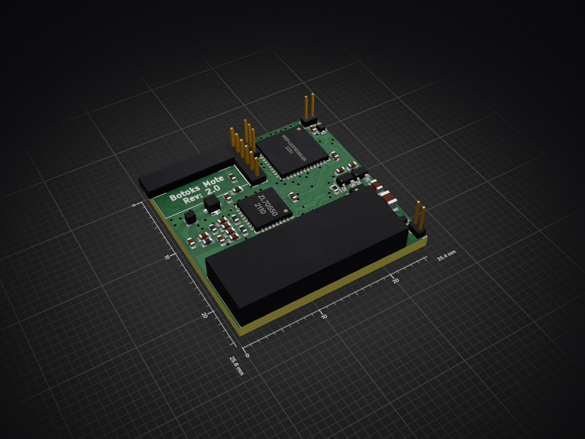
Botox Mote is an open-source printed circuit board by TUDSSL, from the TUDSSL/Botoks repository on GitHub. It is a 4-layer board of 25.4 × 25.6 mm with 109 parts on 113 nets, routed with 1,417 tracks and 140 vias.
It is built around the MSP430FR5994IRGZ, TS3A4751PWR and SN74AUP2G79DCU, with the TLV3691IDCK, S-1313A22-N4T1U3 and SN74AUP2G00DCU among its other parts. Its parts include 44 capacitors, 28 resistors, 18 ICs, 6 inductors and 5 connectors. It belongs with the power boards and the MSP430 boards of this library.


Botoks is a batteryless timekeeping sensor that operates intermittently harvesting ambient energy. Botoks's hardware and software components enable IoT applications that require precise and intermittency-safe timekeeping. Both hardware design and software stack are open-source.
The cascaded hierarchical remanence timekeeper (CHRT) embedded on Botoks is a novel remanence timekeeper architecture. In principle, capacitive remanence timekeepers are simple RC circuits whose energy level is converted into time. To know more about them and the CHRT, refer to our paper (to be made public) and the docs.
The sensor is based on an MSP430 ultra-low-power, FRAM-enabled microcontroller (MSP430FR5994), and currently the software stack only supports this MCU.
apps/               ## Applications' source code
bin/                ## Compiled applications
config/             ## Various configuration files
docs/               ## Source documentation
external/           ## MSP430 base drivers
libs/               ## Core Botoks's libraries
platforms/          ## GPIO pin mappings
scripts/ ## Botoks's calibration scriptsBotoks's code can be built installing the MSP430-GCC toolchain, or using a preconfigured Docker container. Opting for the Docker container has the advantage of not having to install the toolchain, but requires you to mount the directory of the project into the container.
Executables can be uploaded and debugged using UniFlash or Code Composer Studio (CCS). The former method is easier to script, whilst the latter gives you access to a graphical IDE.
The following versions of CMake, MSP430-GCC and UniFlash were tested, but other versions might work as well.
You can use the build_with_docker.sh script to build all applications inside a
Docker container. Install docker on your machine and start/enable the
docker daemon. Moreover, make sure that you can docker commands without
root privileges (check here). The script uses this Docker
image to build applications inside a Docker container
pre-configured with CMake and the MSP430-GCC toolchain.
You can pass -t <target> to the script to specify a target for make. For
instance, to build all projects and install the generated executables in the
bin/ folder of this repository, run
$ ./build_with_docker.sh -t installFirst of all, install CMake and the MSP430-GCC toolchain. CMake can be
installed using your OS's package manager, though the latest version might not
be available. In that case, download the binaries using the link above. As for
the GCC toolchain, you can use the provided install_toolchain.sh script to
download and install toolchain and support files.
To install, do
$ MSP430_GCC_OS=linux64   # can be 'linux32' or 'macos' instead
$ INSTALL_PREFIX=~/ti     # where to install the toolchain
$ ./install_toolchain.sh
This will download toolchain and other support files from TI's website, and
install them at $INSTALL_PREFIX/msp430-gcc. Then, assign the environment
variable MSP430_TOOLCHAIN_PATH the absolute path to the root directory of the
toolchain, e.g.
$ export MSP430_TOOLCHAIN_PATH=~/ti/msp430-gccFinally, to build all projects, do
$ git clone https://github.com/TUDSSL/Botoks.git
$ cd Botoks
$ mkdir build && cd build
$ cmake ..
$ make
Then run make install to build all projects and install the generated
executables in the bin/ folder of this repository. To build applications
individually, run make <app-name>.
First, connect Botoks to a debugger capable of debugging the MSP430 line of products. Then power Botox using the auxiliary power connector on the PCB. The voltage provided needs to be between 3.4 and 5V.
To upload an application install UniFlash. As of now, all scripts
assume UniFlash is installed at /opt/ti/uniflash. From the project's
directory root, run:
$ ./flash.sh bin/<app-name>.outThe serial output can now be monitored using your favorite serial monitor (e.g.,
picocom) with a baudrate of 19200.
$ picocom /dev/ttyACM1 -b 19200 --imap lfcrlfFor the calibration procedure please refer to the docs. Running the
calibration procedure requires a licensed version of MATLAB and the
serial terminal picocom.
The Docker container comes with all the dependencies to build the documentation. Simply run
$ ./build_with_docker.sh -t docsand find the HTML documentation in build/docs/html.
The hardware is designed in KiCad, however, PDF schematics and gerbers are available in the hardware folder.
| Qty | Value | Footprint | References |
|---|---|---|---|
| 20 | 100nF | Capacitor_SMD:C_0402_1005Metric | C1, C4, C22, C23, C24, C27, C28, C29, C30, C31, C32, C33, C34, C37, C38, C44 +4 |
| 11 | 10M | Resistor_SMD:R_0402_1005Metric | R2, R4, R5, R6, R7, R8, R11, R22, R23, R24, R25 |
| 6 | DNP | Capacitor_SMD:C_0402_1005Metric | C2, C3, C17, C21, C39, C43 |
| 5 | 100 | Resistor_SMD:R_0402_1005Metric | R9, R10, R26, R27, R37 |
| 4 | 22M | Resistor_SMD:R_0805_2012Metric | R13, R14, R30, R31 |
| 4 | BAS40-02V-V-G-08 | Diode_SMD:D_SOD-523 | D1, D2, D3, D4 |
| 4 | TS3A4751 | Package_DFN_QFN:Texas_S-PVQFN-N14 | U3, U6, U10, U14 |
| 3 | 100pF | Capacitor_SMD:C_0402_1005Metric | C9, C10, C14 |
| 3 | SN74AUP2G79DCU | Package_SO:VSSOP-8_2.4x2.1mm_P0.5mm | U4, U11, U12 |
| 3 | TLV3691IDCK | jaspers_footprints:Texas_R-PDSO-G5 | U8, U9, U17 |
| 2 | 0.7pF | Capacitor_SMD:C_0402_1005Metric | C12, C13 |
| 2 | 2.2 / 220nF | Capacitor_SMD:C_0805_2012Metric | C25, C35 |
| 2 | 2.2uF | Capacitor_SMD:C_0402_1005Metric | C15, C18 |
| 2 | 22 nF / 2.2uF | Capacitor_SMD:C_0805_2012Metric | C26, C36 |
| 2 | 39nH | Inductor_SMD:L_0402_1005Metric | L3, L4 |
| 2 | 39pF | Capacitor_SMD:C_0402_1005Metric | C8, C11 |
| 2 | 8.7nH | Inductor_SMD:L_0402_1005Metric | L1, L2 |
| 2 | Conn_01x02 | Connector_PinHeader_1.00mm:PinHeader_1x02_P1.00mm_Vertical | J3, J5 |
| 2 | S-1313A22-N4T1U3 | Package_TO_SOT_SMD:SC-82AB | U1, U18 |
| 2 | SN74AUP2G00DCU | Package_SO:VSSOP-8_2.4x2.1mm_P0.5mm | U5, U13 |
| 1 | 1.1M | Resistor_SMD:R_0402_1005Metric | R35 |
| 1 | 1.5M | Resistor_SMD:R_0402_1005Metric | R33 |
| 1 | 100uF | Capacitor_SMD:C_0805_2012Metric | C42 |
| 1 | 10k | Resistor_SMD:R_0402_1005Metric | R36 |
| 1 | 10u | Capacitor_SMD:C_0805_2012Metric | C20 |
| 1 | 19nH | Inductor_SMD:L_0402_1005Metric | L5 |
| 1 | 2.2nF | Capacitor_SMD:C_0402_1005Metric | C40 |
| 1 | 2.4M | Resistor_SMD:R_0402_1005Metric | R16 |
| 1 | 22uF | Capacitor_SMD:C_0603_1608Metric | C41 |
| 1 | 360k | Resistor_SMD:R_0402_1005Metric | R34 |
| 1 | 47k | Resistor_SMD:R_0402_1005Metric | R32 |
| 1 | 49.9k ±1% | Resistor_SMD:R_0402_1005Metric | R1 |
| 1 | 7.5nH | Inductor_SMD:L_0402_1005Metric | L6 |
| 1 | 9.1M | Resistor_SMD:R_0402_1005Metric | R15 |
| 1 | 952-3602-ND | Connector_PinHeader_1.27mm:PinHeader_1x06_P1.27mm_Vertical | J1 |
| 1 | C | Capacitor_SMD:C_0402_1005Metric | C16 |
| 1 | Conn_01x03 | Connector_PinHeader_1.00mm:PinHeader_1x03_P1.00mm_Vertical | J2 |
| 1 | ECS-240-8-37CKM | jaspers_footprints:ECX-1637 | Y1 |
| 1 | KXOB25-02X8F | jaspers_footprints:KXOB25-02X8F | SC1 |
| 1 | MCP1810T-12 | Package_TO_SOT_SMD:SOT-23-5 | U7 |
| 1 | MIC841HYC5 | jaspers_footprints:SC70-5 | U16 |
| 1 | MM8030-2610 | jaspers_footprints:MM8030 | J4 |
| 1 | MSP430FR5994IRGZ | Package_DFN_QFN:QFN-48-1EP_7x7mm_P0.5mm_EP5.15x5.15mm | U15 |
| 1 | SF16-0868M4 | jaspers_footprints:SF16-0868M4 | F1 |
| 1 | W3016 | jaspers_footprints:W3016 | AE1 |
| 1 | ZL70550 | jaspers_footprints:QFN-32-1EP_5x5mm_P0.5mm_EP3.45x3.45mm_ThermalVias_0.3mm_Drill | U2 |
It measures 25.4 × 25.6 mm and has 4 copper layers, 1.6 mm thick.
109 parts, built around the MSP430FR5994IRGZ, TS3A4751PWR, SN74AUP2G79DCU and TLV3691IDCK. The full list of its parts is on this page, with links to each part's symbol and footprint where PCBKit's library has them.
From the TUDSSL/Botoks repository on GitHub, at the commit this page was made from: the board is hardware/Botox_Mote.kicad_pcb. PCBKit opens the board in the browser, with nothing to install.
Its repository states no licence, so its author keeps all rights: ask TUDSSL before reusing the design.


punkfab/pcb-corpus
235 real KiCad boards from open-source hardware repositories, prepared as a placement and routing benchmark

jfhansen/3-Phased-Inverter-for-Electric-Gokart
Repository containing Simulation files, PCB files and embedded software for three-phased inverter drive.


Galacs/motor-power-poc
A POC PCB to test circuit electrical protections and motor control schemes

MZMurad/X-band_Transmitter_Thesis_Files
This is a repo for all the files used and mentioned in my thesis

PicoballoonLabs/Debug-Boards
Hardware designs for the integrated debug probe, debug adapter, flex debug cables and RF VNA calibrator