Skip to the content
PCBKitNew board
2 layers21.1 × 45.7 mmRP2040-base example, the printed circuit board in 3D

RP2040-base example

TT-392/RP2040-base-example

Revision 0.9 was produced at jlcpcb. The rev number was bumped to 1.0 after the pcb was tested. There were no changes between rev 0.9 and 1.0.

Size
21.1 × 45.7 mm
Copper layers
2
Thickness
1.6 mm
Parts
34
Nets
54
Pads
175
Tracks, vias
282, 45
Pours
5
Routed
Yes
KiCad
KiCad 7 (file 20221018)
Created
30 Jul 2023
Updated
4 Jan 2024

Overview

RP2040-base example is an open-source printed circuit board by TT-392, from the TT-392/RP2040-base-example repository on GitHub. It is a 2-layer board of 21.1 × 45.7 mm with 34 parts on 54 nets, routed with 282 tracks and 45 vias.

It is built around the RP2040, SRV05-4 and XC6206P332MR, with the GT-USB-7047C and X322512MSB4SI among its other parts. Its parts include 18 capacitors, 6 resistors, 4 ICs, 4 connectors and 1 switch. It belongs with the RP2040 boards of this library.

Main components

5

README

README.md

RP2040-base-example

A simple dev board, created to test RP2040-base

Revision 0.9 was produced at jlcpcb. The rev number was bumped to 1.0 after the pcb was tested. There were no changes between rev 0.9 and 1.0. The production files in the "jlcpcb" folder are identical to the ones used to order the pcbs.

There seems to be one serious bug in the design, see "known issues" nr 1
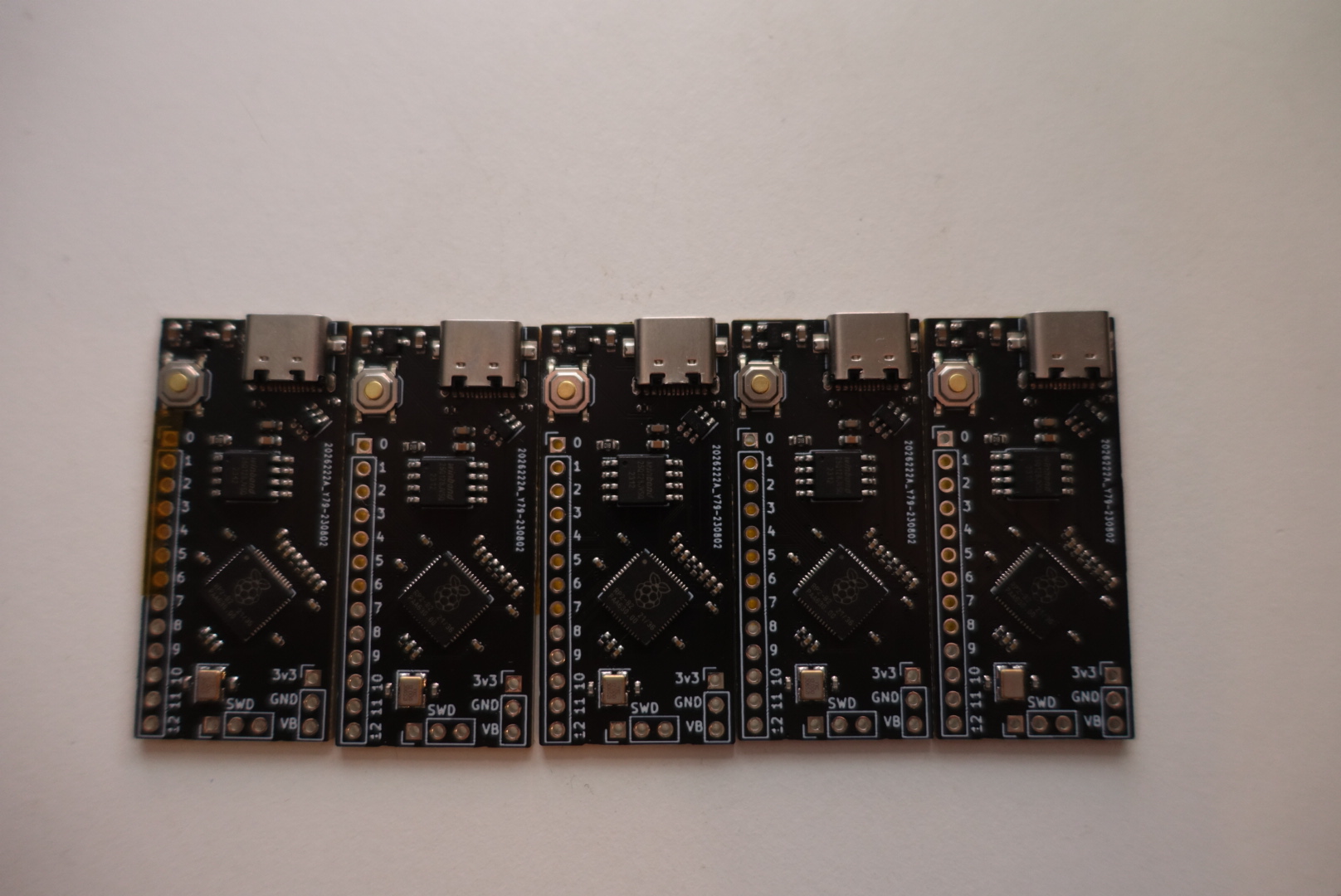
5 pcbs of revision 0.9 with black solder mask revision 0.9 of the pcb

Tested functionality physical board rev 0.9 (identical to 1.0)

A sketch has been uploaded, which prints a string over cdc usb every second. This indicates working usb functionality, and working program memory.

After unplugging and plugging the board back in, the board doesn't seem to correctly start, see known issue nr 1.

Notes

  • jlcpcb has no basic part 27 ohm resistors, therefore, when ordering the test pcbs, the series termination resistors on the usb lines were replaced with 22 ohm ones (not too critical but not ideal)

Known issues

  1. There is something wrong with the chrystal setup, experiences the same issues as the adafruid boards mentioned in: https://github.com/raspberrypi/pico-sdk/pull/457. This can be fixed by setting PICO_XOSC_STARTUP_DELAY_MULTIPLIER to 64, like mentioned there.
  2. No thought was given to which IO pins should be exposed, no analog pins have been exposed.
  3. No debug LED.
  4. ground plane on top layer wasn't taken into account when calculating trace with for usb line impedance matching (not too critical but not ideal)

Parts

34
QtyValueFootprintReferences
10100nCapacitor_SMD:C_0402_1005MetricC3, C4, C5, C6, C7, C8, C9, C10, C11, C12
21uCapacitor_SMD:C_0402_1005MetricC13, C14
21uCapacitor_SMD:C_0603_1608MetricC1, C2
227Resistor_SMD:R_0402_1005MetricR3, R4
230pCapacitor_SMD:C_0402_1005MetricC15, C16
25k1Resistor_SMD:R_0402_1005MetricR1, R2
2Conn_01x03Connector_PinHeader_2.54mm:PinHeader_1x03_P2.54mm_VerticalJ1, SWD1
1100nCapacitor_SMD:C_0603_1608MetricC17
110nCapacitor_SMD:C_0603_1608MetricC18
11kResistor_SMD:R_0402_1005MetricR5
11kResistor_SMD:R_0603_1608MetricR6
1Conn_01x13Connector_PinHeader_2.54mm:PinHeader_1x13_P2.54mm_VerticalJ2
1GT-USB-7047Cfootprints:GT-USB-7047CJ3
1RP2040Package_DFN_QFN:QFN-56-1EP_7x7mm_P0.4mm_EP3.2x3.2mmU3
1SRV05-4footprints:SOT-23-6_flipped_for_jlcpcbU2
1SW_PushRP2040_base:TS-1187ASW1
1W25QXXXJVRP2040_base:SOIC-8_5.275x5.275mm_P1.27mmU4
1X322512MSB4SIRP2040_base:YSX321SL, datasheet recommended measurementsY1
1XC6206P332MRfootprints:SOT-23-3_flipped_for_jlcpcbU1

Questions

How big is the RP2040-base example PCB?

It measures 21.1 × 45.7 mm and has 2 copper layers, 1.6 mm thick.

What parts does the RP2040-base example use?

34 parts, built around the RP2040, SRV05-4, XC6206P332MR and GT-USB-7047C. The full list of its parts is on this page, with links to each part's symbol and footprint where PCBKit's library has them.

Where can I download the RP2040-base example KiCad files?

From the TT-392/RP2040-base-example repository on GitHub, at the commit this page was made from: the board is RP2040_base_example.kicad_pcb and its schematic RP2040-base/RP2040_base.kicad_sch. PCBKit opens the board in the browser, with nothing to install.

Can I use the RP2040-base example design in my own project?

Its repository states no licence, so its author keeps all rights: ask TT-392 before reusing the design.

Similar boards

  • 2 layers26.1 × 56.7 mmPlaystation adapter, the printed circuit board in 3D

    Playstation adapter

    TT-392/playstation_adapter_pcb

    I only wrote software for the Taiko drum, but in theory, all of the hardware is there to support a lot of different kinds of PlayStation controllers. The firmware can be found here.

    39 parts
  • 2 layers269.9 × 93.1 mmGear40, the printed circuit board in 3D

    Gear40

    cosmosalad/GearSeries

    All Gear series keyboards are being uploaded.

    217 parts6
  • 2 layers209.6 × 66.7 mmLittolRP2040, the printed circuit board in 3D

    LittolRP2040

    baconspoon85/littol

    3 row 30% katakana with exploded spacebar

    81 parts4
  • 2 layers284.2 × 93.7 mmGear60 solder, the printed circuit board in 3D

    Gear60 solder

    cosmosalad/Gear60

    Gear60 is a 60% multi-layout keyboard based on the rp2040.

    198 parts4MIT
  • 2 layers285.1 × 94.6 mmYM60JIS PCB, the printed circuit board in 3D

    YM60JIS PCB

    ymkn/YM60JIS

    A JIS layout 60% hot swappable custom mechanical keyboard PCB powered by RP2040.

    173 parts10MIT
  • 2 layers353.1 × 124.9 mmSkeleton68rev2, the printed circuit board in 3D

    Skeleton68rev2

    skeletonkbd/Frost68

    252 parts5
  • 2 layers285.1 × 94.6 mmYuTofu PCB, the printed circuit board in 3D

    YuTofu PCB

    ymkn/YuTofu

    YuTofu is an unofficial compatible PCB for the well-known custom keyboard Tofu60 2.0.

    169 parts5MIT