2 layers54.1 × 21.9 mm
 Tropaion/ZigBee_SmartMeter_Reader32
This is a ZigBee device to collect data from smartmeters using the DLMS/COSEM protocol.
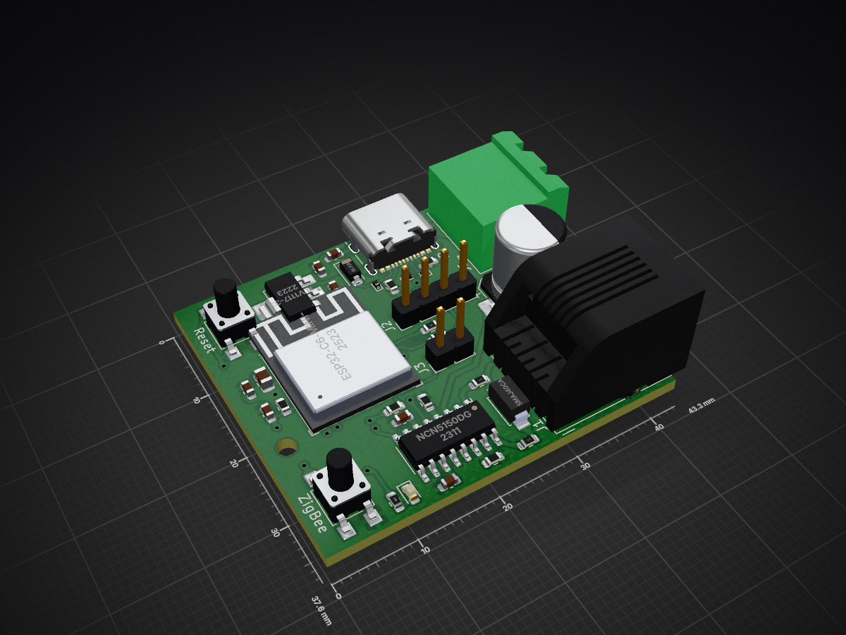
ZBSmartMeter is an open-source printed circuit board by Tropaion, from the Tropaion/ZigBee_SmartMeter_Reader repository on GitHub, published under the GPL-3.0 licence. It is a 2-layer board of 43.3 × 37.6 mm with 37 parts on 58 nets, routed with 169 tracks and 20 vias.
It is built around the ESP32-C6-MINI-1U-H4, TLV1117-33DCY and CPDQ5V0-HF, with the SMAJ40CA among its other parts. Its parts include 11 resistors, 9 capacitors, 6 diodes, 5 connectors and 3 ICs. It belongs with the radio and wireless and home automation and IoT boards and the ESP32 and RISC-V boards of this library.


This is an open-source ZigBee device based on the new ESP32-C6 to collect data from smartmeters using the DLMS/COSEM protocol.
Ever since I got the smartmeter "Sagemcom T-210D" with the P1 user interface, I wanted to integrate it into my ZigBee network. Since I didn't find any existing solution, I decided to develop my own.
If someone is interested in buying an assembled PCB, pm me. Currently I have one board with external antenna available.
THE PROJECT IS STILL WIP.
View the latest PCB Interactive BOM.
You can also view the latest Schematic or Layout.
The same hardware could also be used with WLAN and ESPHome.


For this project, I used the ESP32-C6-MINI-1U. I chose the version with an external antenna, since, in most cases, the devices will be mounted in an isolated meter box. And, since many of them are made of metal (Faraday cage), like in my case, I opted for an external antenna to mount on the outside of the meter box.
To provide easy flashing and debugging the USB-C-Socket is connected to the ESP internal USB-JTAG-Converter. In the case that the converter is not working, the UART0 programming interface is connected to J2 and J3, which will not be assembled.
For production use in the meter box, only the 5V supply terminal (J5) which in my case will be connected to a 5V DIN Power Supply and RJ12 (J1) cable going to the smartmeter is needed.
Since most smartmeters send encrypted data, you probably need to request an decryption key from your provider. This key has to be configured in the software. The current plan for this is to provide a simple configuration terminal which is accessible via the USB-C-Socket.
The software will be separated into three core components/libraries. Each will be individually tested and then combined.
Possible additional functionalities:
OR
How the data is handled is a bit complicated and consists of three layers:
Each layer will be handled by a parser.
See the diagram to understand the structure and how the parser handles the data:

The first version of the enclosure is released and now in printing.

Thanks to EspressIf for sponsoring two samples of ESP32-C6-MINI-1U.
Thanks to PCBWay for sponsoring the production of the PCB and Stencil for v0.2. It was my first time using their service and they have nice customer service and great build quality. The image in the hardware section shows the result of v0.2.
| Qty | Value | Footprint | References |
|---|---|---|---|
| 3 | CPDQ5V0-HF | Diode_SMD:D_SOD-923 | D4, D5, D6 |
| 2 | 10kΩ 1% | Resistor_SMD:R_0603_1608Metric | R5, R6 |
| 2 | 160Ω | Resistor_SMD:R_0603_1608Metric | R8, R9 |
| 2 | 1µF/10V | Capacitor_SMD:C_0603_1608Metric | C5, C6 |
| 2 | 220Ω | Resistor_SMD:R_0603_1608Metric | R1, R2 |
| 2 | 5.1kΩ 1% | Resistor_SMD:R_0603_1608Metric | R10, R11 |
| 2 | SW_Push | Button_Switch_SMD:SW_SPST_TL3305A | SW1, SW2 |
| 1 | 0.1µF/50V/10% | Capacitor_SMD:C_0603_1608Metric | C8 |
| 1 | 100Ω 1% | Resistor_SMD:R_0603_1608Metric | R4 |
| 1 | 10µF | Capacitor_SMD:C_0603_1608Metric | C1 |
| 1 | 10µF/25V/20% | Capacitor_SMD:C_0603_1608Metric | C9 |
| 1 | 1N5819 | Diode_SMD:D_SOD-123 | D3 |
| 1 | 1µF/16V/10% | Capacitor_SMD:C_0603_1608Metric | C4 |
| 1 | 220nF | Capacitor_SMD:C_0603_1608Metric | C2 |
| 1 | 22µF/10V | Capacitor_SMD:C_0805_2012Metric | C7 |
| 1 | 30kΩ 1% | Resistor_SMD:R_0603_1608Metric | R3 |
| 1 | 330µF 10% | Capacitor_SMD:CP_Elec_8x10.5 | C3 |
| 1 | 680Ω | Resistor_SMD:R_0603_1608Metric | R7 |
| 1 | Conn_01x02 | Connector_PinHeader_2.54mm:PinHeader_1x02_P2.54mm_Vertical | J3 |
| 1 | Conn_01x04 | Connector_PinHeader_2.54mm:PinHeader_1x04_P2.54mm_Vertical | J2 |
| 1 | ESP32-C6-MINI-1/U | Espressif:ESP32-C6-MINI-1U | U3 |
| 1 | LEDmA | LED_SMD:LED_0603_1608Metric | D2 |
| 1 | MountingHole | MountingHole:MountingHole_2.2mm_M2 | H1 |
| 1 | NCN5150DG | Package_SO:SOIC-16_3.9x9.9mm_P1.27mm | U1 |
| 1 | RJ12 | Connector_RJ:RJ12_Amphenol_54601 | J1 |
| 1 | SMAJ40CA | SMAJ40CA:DIOM4325X250N | D1 |
| 1 | Screw_Terminal_01x02 | Connector_Phoenix_MSTB:PhoenixContact_MSTBA_2,5_2-G_1x02_P5.00mm_Horizontal | J5 |
| 1 | TLV1117-33 | Package_TO_SOT_SMD:SOT-223-3_TabPin2 | U2 |
| 1 | USB_C_Receptacle_USB2.0 | Connector_USB:USB_C_Receptacle_GCT_USB4105-xx-A_16P_TopMnt_Horizontal | J6 |
It measures 43.3 × 37.6 mm and has 2 copper layers, 1.6 mm thick.
37 parts, built around the ESP32-C6-MINI-1U-H4, TLV1117-33DCY, CPDQ5V0-HF and SMAJ40CA. The full list of its parts is on this page, with links to each part's symbol and footprint where PCBKit's library has them.
From the Tropaion/ZigBee_SmartMeter_Reader repository on GitHub, at the commit this page was made from: the board is hardware/external_antenna/ZBSmartMeter.kicad_pcb and its schematic hardware/external_antenna/ZBSmartMeter.kicad_sch. PCBKit opens the board in the browser, with nothing to install.
Its repository publishes it under the GPL-3.0 licence: you may reuse it on that licence's terms (keep the author's notice, and for a copyleft licence share your changes alike).

dsg-jam/chrononauts-quest
This sub-folder contains the hardware design files for an RF transceiver system built using an ESP32-C3 module and a CC1101 RF chip.


MrBlahhhh/esp32-shield-can1-can2-kdcan-analogin-sdcard
A carrier board an ESP32-S3-DevKitC-1 plugs into, turning it into a vehicle data logger. The dev board brings the MCU and its power; this board brings everything that has to touch a car.


andrzejkasica/CO-sensor
Project based on ME2-CO gas sensor with current loop and 2 relays output.