8 layers
FIRM v1.1
NCSU-High-Powered-Rocketry-Club/FIRM-KiCad
Full and open hardware design for FIRM
108 parts1MIT

 TravisBumgarner/pixels64
Pixels64 is an 8x8 grid of 64 individually addressable RGB LEDs using the WS2812B package. It’s powered by an ESP32 running CircuitPython with the neopixel library for control. It features a custom-designed circuit board and a 3D-printable housing.
Pixels64 is an open-source printed circuit board by TravisBumgarner, from the TravisBumgarner/pixels64 repository on GitHub. It is a 2-layer board of 100 × 100 mm with 40 parts on 19 nets, routed with 289 tracks and 16 vias.
It is built around the CL10B104KA8NNN and WS2812B-MINI-V3/W. Its parts include 16 capacitors and 16 diodes. It belongs with the lEDs and displays boards and the ESP32 boards of this library.


Pixels64 is an 8x8 grid of 64 individually addressable RGB LEDs using the WS2812B package. It’s powered by an ESP32 running CircuitPython with the neopixel library for control. It features a custom-designed circuit board and a 3D-printable housing.
(Need help? Join the community!)
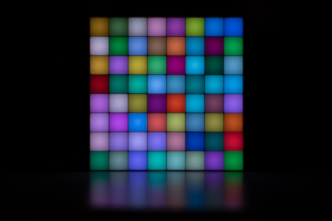
This repository includes all the files needed to build the Pixel64 display.
cad - 3D models for housingcircuit - PCB diagram and schematiccode - Code for showing various displaysweb - Browser control UI, pairs with bluetooth-experimental over Web Bluetoothdisplays Collection of displays to get inspired. Check them out on Instagram.Additionally
my_displays - What I am currently tinkering on to display.The PCB is designed to be modular, allowing multiple boards to be combined in an N x M configuration for any display size.
base-plate.stl and walls.stl in black. Print case.stl in white.jlcpcb and order from JLCPCBDataIn1 of the first PCB.Dataout1 to the DataIn1 of the next PCB.base-plate.stl.DataIn1 at the bottom.3 4
1 2python -m venv venv inside the code directorypip install -r requirements.txtesptool.py --chip esp32 --port [device] erase_flashesptool.py --chip esp32 --port [device] --baud 460800 write_flash -z 0x1000 file.uf2write.sh script to upload files to device.en button to shuffle the displays.case.stl services as the "screen" of the pixel64. It can be challenging to get a clean print of such a size. You'll need very good first layer adhesion. An alternative here would be to make a case out of white acrylic instead or cover the walls with a white sheet of paper.ls /dev/cu.* /dev/tty.*tty.usbserial-0001mpremoteprint statement while uploading code.mpremote.ctrl + ] to exitctrl + c and ctrl + d to soft reboot and cycle through displays.ampy --port /dev/tty.usbserial-0001 put boot.pyput fails, reconnect device.ampy --port /dev/tty.usbserial-0001 rm boot.pyampy --port /dev/tty.usbserial-0001 lsThe LED circuit board I designed supports multiple configurations, meaning the default ordering of NeoPixels may not match the expected layout. For example, setting neopixel[0] = (255, 255, 255) won't necessarily light up the top-left LED.
This script cycles through each pixel one at a time, allowing you to determine the actual order. Once identified, we can remap the ordering. For example, the physical layout might be:
 3  2  1  0
 7  6  5  4
11 10  9  8
15 14 13 12
We can then transform it into a more intuitive sequence:
 0  1  2  3
 4  5  6  7
 8  9 10 11
12 13 14 15
This remapping ensures easier indexing and consistent control over the LEDs.
Take the following code and save it to main.py
import machine
import time
import neopixel

NEO_PIXEL_PIN = 13
NEO_PIXEL_COUNT = 64

neo_pin = machine.Pin(NEO_PIXEL_PIN, machine.Pin.OUT)
np = neopixel.NeoPixel(neo_pin, NEO_PIXEL_COUNT)


def set_pixel(i, r, g, b):
    np[i] = (r, g, b)
    np.write()


def main():
    while True:
        for i in range(64):
            set_pixel(i, 255, 0, 0)
            time.sleep_ms(2000)
            set_pixel(i, 0, 0, 0)


if __name__ == "__main__":
    main()
Upload the code to the esp32
ampy --port [replace with your device] put main.pyPlace a sheet of paper over the LEDs and tape in place.
Press the en button on the esp32 to run the code.
You should see the LEDs light up in a red color.
Mark the first LED that lights up as 0 and complete until done.
Now, starting from the top left, write the numbers of the LEDs in a left to right top to bottom order in the config.py file, replacing the variable LOOKUP.
| Qty | Value | Footprint | References |
|---|---|---|---|
| 16 | C1590 | Capacitor_SMD:C_0805_2012Metric | C1, C2, C3, C4, C5, C6, C7, C8, C9, C10, C11, C12, C13, C14, C15, C16 |
| 16 | C527089 | LED_SMD:LED_WS2812B-Mini_PLCC4_3.5x3.5mm | D1, D2, D3, D4, D5, D6, D7, D8, D9, D10, D11, D12, D13, D14, D15, D16 |
| 4 | Conn_01x03_Pin | Connector_PinHeader_2.54mm:PinHeader_1x03_P2.54mm_Vertical | DataIn1, DataOut0, DataOut1, DataOut2 |
| 4 | MountingHole | MountingHole:MountingHole_3.2mm_M3_DIN965_Pad | H1, H2, H3, H4 |
It measures 100 × 100 mm and has 2 copper layers, 1.6 mm thick.
40 parts, built around the CL10B104KA8NNN and WS2812B-MINI-V3/W. The full list of its parts is on this page, with links to each part's symbol and footprint where PCBKit's library has them.
From the TravisBumgarner/pixels64 repository on GitHub, at the commit this page was made from: the board is circuit/v1.0/kicad/kicad.kicad_pcb and its schematic circuit/v1.0/kicad/kicad.kicad_sch. PCBKit opens the board in the browser, with nothing to install.
Its repository states no licence, so its author keeps all rights: ask TravisBumgarner before reusing the design.
NCSU-High-Powered-Rocketry-Club/FIRM-KiCad
Full and open hardware design for FIRM


hackclub/OnBoard
💡 Join 1,000 teenagers and make your first PCB with a $100 grant!

Chrismettal/EleLab_v2
Cheap DIY lab system for hobbyists and the tinkering folk

Chrismettal/flipper-zero-backpacks
Backpack-style addon boards for the Flipper Zero!

