2 layers70.9 × 38.1 mm

 trailcurrentoss/TrailCurrentTorrent
CAN bus controlled power distribution module for vehicle electrical circuits
TrailCurrentTorrent is an open-source printed circuit board by trailcurrentoss, from the trailcurrentoss/TrailCurrentTorrent repository on GitHub, published under the MIT licence. It is a 2-layer board of 134.7 × 91.9 mm with 68 parts on 78 nets, routed with 642 tracks and 376 vias.
It is built around the ESP32-WROOM-32, SN65HVD230D and IRF4905STRLPBF, with the SS54 among its other parts. Its parts include 19 resistors, 14 connectors, 11 ICs, 8 diodes and 8 transistors. It belongs with the interfaces and adapters and home automation and IoT boards and the ESP32 boards of this library.


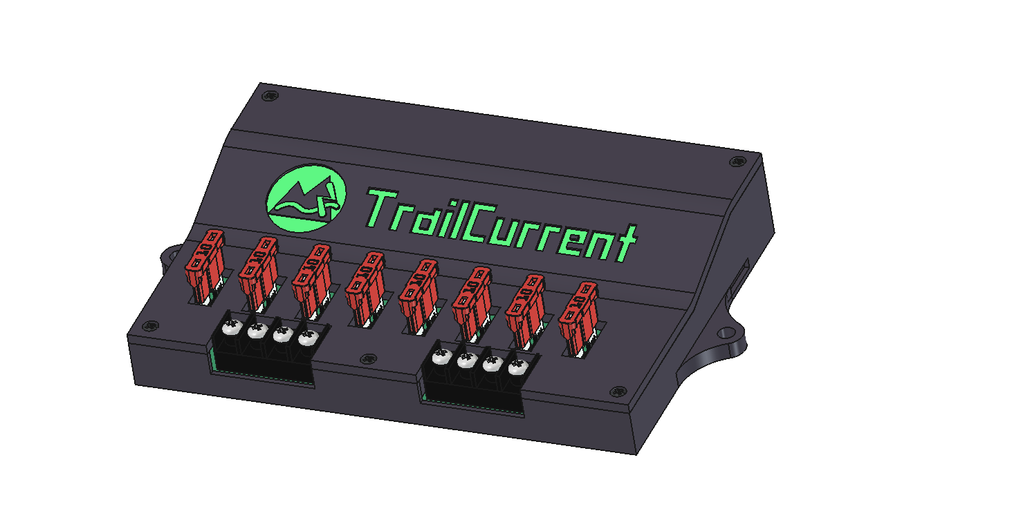
CAN-controlled 8-channel PWM power distribution module for vehicle lighting and accessory control with OTA firmware update capability and mDNS self-discovery. Up to 3 Torrent modules can operate on the same CAN bus, each with a unique address and CAN IDs. Part of the TrailCurrent open-source vehicle platform.
TORRENT_ADDRESS (0-2)PWM Outputs:
| GPIO | Function |
|---|---|
| 32 | Output 1 |
| 33 | Output 2 |
| 26 | Output 3 |
| 14 | Output 4 |
| 4 | Output 5 |
| 17 | Output 6 |
| 19 | Output 7 |
| 23 | Output 8 |
This project uses the consolidated TrailCurrentKiCADLibraries.
Setup:
# Clone the library
git clone git@github.com:trailcurrentoss/TrailCurrentKiCADLibraries.git

# Set environment variables (add to ~/.bashrc or ~/.zshrc)
export TRAILCURRENT_SYMBOL_DIR="/path/to/TrailCurrentKiCADLibraries/symbols"
export TRAILCURRENT_FOOTPRINT_DIR="/path/to/TrailCurrentKiCADLibraries/footprints"
export TRAILCURRENT_3DMODEL_DIR="/path/to/TrailCurrentKiCADLibraries/3d_models"
See KICAD_ENVIRONMENT_SETUP.md in the library repository for detailed setup instructions.
kicad EDA/trailcurrent-torrent.kicad_proAlt+3 to view the 3D visualizationThe design uses a hierarchical schematic with dedicated sheets:
Built with ESP-IDF (Espressif IoT Development Framework) targeting the ESP32.
Install ESP-IDF v5.x following the official guide.
# Set up ESP-IDF environment
source ~/esp/v5.5.2/esp-idf/export.sh

# First time: set chip target
idf.py set-target esp32

# Build firmware (default address 0)
idf.py build

# Build for a specific module address (0-2)
idf.py build -DTORRENT_ADDRESS=1

# Flash and monitor (serial)
idf.py -p /dev/ttyUSB0 flash monitorUp to 3 Torrent modules can share the same CAN bus. Each module is built with a unique address that determines its CAN IDs:
idf.py build                      # Address 0 (default)
idf.py build -DTORRENT_ADDRESS=1  # Address 1
idf.py build -DTORRENT_ADDRESS=2  # Address 2
Each address produces a firmware binary with unique CAN IDs (see CAN Bus Protocol below). Flash each binary to a different ESP32. At boot, the module logs its address and CAN IDs for verification.
Use build-all.sh to build all 3 address variants in a single run:
./build-all.shThis produces two binaries per address — one for OTA updates, one for the web flasher:
| File | Contents | Used By |
|---|---|---|
build/torrent_addr{N}.bin | Application image only | Headwaters OTA (deploy.sh, ota.js), direct curl uploads |
build/torrent_addr{N}_merged.bin | Bootloader + partition table + OTA data + application | Web flasher (full flash at 0x0) |
The two binary types exist because OTA and the web flasher write to different targets. Headwaters OTA sends the binary to the device's /ota HTTP endpoint, which calls esp_ota_write to write it to a single app partition. That function validates the image as an application — a merged binary starts with the bootloader instead of an app header, so it would fail validation. The web flasher writes the entire flash contents starting at offset 0x0, so it needs all partitions combined into one file.
After building all variants, attach all 6 binaries (3 app-only + 3 merged) as release assets:
git tag -a v1.0.0 -m "Firmware release v1.0.0"
git push origin v1.0.0

gh release create v1.0.0 \
  build/torrent_addr0.bin \
  build/torrent_addr1.bin \
  build/torrent_addr2.bin \
  build/torrent_addr0_merged.bin \
  build/torrent_addr1_merged.bin \
  build/torrent_addr2_merged.bin \
  --repo trailcurrentoss/TrailCurrentTorrent \
  --title "v1.0.0" \
  --notes "Firmware release v1.0.0"
Both the Headwaters deployment system and the web flasher pull from GitHub releases. The web flasher matches _merged.bin files by name for full-flash use. The Headwaters deployment system (fetch-firmware.sh) downloads the app-only torrent_addr{N}.bin files for OTA delivery.
After initial serial flash, firmware can be updated over WiFi:
torrent_addr{N}.bin), never the merged binary:
curl -X POST http://esp32-XXYYZZ.local/ota --data-binary @build/torrent_addr0.binThe device enters OTA mode for 3 minutes, starts an HTTP server, and advertises via mDNS. After a successful upload it reboots into the new firmware. Dual OTA partitions provide rollback safety.
Modules register themselves with the Headwaters controller:
_trailcurrent._tcp mDNS service with metadata:
type=torrent — module typeaddr=0 — module address (0-2, from TORRENT_ADDRESS build flag)canid=0x1B — CAN status message ID (varies by address)fw=1.0.0 — firmware versionGET /discovery/confirmDiscovery can be triggered again on subsequent CAN 0x02 broadcasts. A module that is already running a discovery session ignores additional triggers until the current session completes or times out (3 minutes).
Firmware uses the ESP-IDF logging system (ESP_LOGI, ESP_LOGW, ESP_LOGE). Log output is available on the serial monitor at 115200 baud.
Log verbosity can be configured at build time via idf.py menuconfig under Component config > Log output.
WiFi Credentials:
CAN IDs are computed as BASE + TORRENT_ADDRESS. The table below shows base IDs and per-instance values.
Receive (Bus → Module):
| Base ID | Addr 0 | Addr 1 | Addr 2 | Description |
|---|---|---|---|---|
| — | 0x00 | 0x00 | 0x00 | OTA update trigger (3 bytes: last 3 MAC bytes for device targeting) |
| — | 0x01 | 0x01 | 0x01 | WiFi credential provisioning (chunked SSID/password protocol) |
| — | 0x02 | 0x02 | 0x02 | Discovery trigger (broadcast, no payload) |
| — | 0x04 | 0x04 | 0x04 | Version report on boot: [mac3, mac4, mac5, major, minor, patch] |
| 0x15 | 0x15 | 0x16 | 0x17 | Set brightness (byte 0 = channel 0-7, byte 1 = PWM value 0-255) |
| 0x18 | 0x18 | 0x19 | 0x1A | Toggle channel on/off (byte 0 = channel 0-7, 8=all off/on, 9=all on) |
| 0x33 | 0x33 | 0x34 | 0x35 | Trigger light sequence (byte 0: 0=interior, 1=exterior) |
Transmit (Module → Bus):
| Base ID | Addr 0 | Addr 1 | Addr 2 | Interval | Description |
|---|---|---|---|---|---|
| 0x1B | 0x1B | 0x1C | 0x1D | 33 ms (30 Hz) | Status report — current PWM values for all 8 channels (8 bytes) |
WiFi credentials are sent over CAN in chunks (max 6 payload bytes per CAN frame):
| Step | data[0] | Payload | Description |
|---|---|---|---|
| 1 | 0x01 | ssid_len, pass_len, ssid_chunks, pass_chunks | Start message |
| 2 | 0x02 | chunk_index, up to 6 bytes | SSID chunk |
| 3 | 0x03 | chunk_index, up to 6 bytes | Password chunk |
| 4 | 0x04 | XOR checksum | End/commit message |
All messages are sent on CAN ID 0x01. A 5-second timeout resets the state machine if the sequence is interrupted.
├── EDA/                          # KiCAD hardware design files
│   ├── trailcurrent-torrent.kicad_pro
│   ├── trailcurrent-torrent.kicad_sch  # Root schematic
│   ├── can.kicad_sch             # CAN subsystem
│   ├── mcu.kicad_sch             # MCU subsystem
│   ├── power.kicad_sch           # Power subsystem
│   ├── mosfets.kicad_sch         # 8-channel MOSFET drivers
│   ├── dip_switch.kicad_sch      # Configuration switches
│   └── trailcurrent-torrent.kicad_pcb  # PCB layout
├── CAD/                          # FreeCAD case design and 3D models
│   ├── trailcurrent-torrent-case.FCStd
│   └── TrailCurrentTorrent.3mf
├── main/                         # ESP-IDF firmware source
│   ├── main.c                    # App entry, LEDC PWM, TWAI CAN task, light sequences
│   ├── ota.h / ota.c             # OTA updates, WiFi management, credential provisioning
│   ├── discovery.h / discovery.c # mDNS self-discovery and Headwaters registration
│   ├── CMakeLists.txt            # Component build config
│   └── idf_component.yml         # ESP-IDF component dependencies
├── partitions.csv                # ESP32 flash partition layout (dual OTA)
├── sdkconfig.defaults            # ESP-IDF build defaults
├── build-all.sh                  # Build all 3 address variants (addr 0-2)
└── CMakeLists.txt # Root ESP-IDF project configMIT License - See LICENSE file for details.
This is open source hardware. You are free to use, modify, and distribute these designs under the terms of the MIT license.
Improvements and contributions are welcome! Please submit issues or pull requests.
For questions about:
| Qty | Value | Footprint | References |
|---|---|---|---|
| 10 | 10k | Resistor_SMD:R_1206_3216Metric_Pad1.30x1.75mm_HandSolder | R1, R4, R6, R9, R11, R13, R15, R17, R19, R21 |
| 8 | 470 | Resistor_SMD:R_1206_3216Metric_Pad1.30x1.75mm_HandSolder | R7, R8, R10, R12, R14, R16, R18, R20 |
| 8 | Conn_01x04 | Fuse:Automotive_Fuse_Holder | J4, J5, J6, J7, J9, J10, J11, J12 |
| 8 | IRF4905STRLPBF | Transistor_Power:IRF4905STRLPBF | Q1, Q2, Q3, Q4, Q5, Q6, Q7, Q8 |
| 8 | PC817 | OptoDevice:PC817X3CSP9F | U4, U5, U6, U7, U8, U9, U10, U11 |
| 8 | SS54 | Diode_SMD:D_SMB | D1, D2, D3, D4, D5, D6, D7, D8 |
| 3 | 22uF | Capacitor_SMD:C_1206_3216Metric_Pad1.33x1.80mm_HandSolder | C1, C5, C6 |
| 2 | Conn_01x01 | TestPoint:TestPoint_7.77mmX7.77mm | J13, J14 |
| 2 | Conn_01x04 | Connector:Screw_Terminal_1x04 | J3, J8 |
| 1 | 0.1uF | Capacitor_SMD:C_1206_3216Metric_Pad1.33x1.80mm_HandSolder | C2 |
| 1 | 100nF | Capacitor_SMD:C_1206_3216Metric | C4 |
| 1 | 10uF | Capacitor_SMD:C_1206_3216Metric | C3 |
| 1 | 120 | Resistor_SMD:R_1206_3216Metric_Pad1.30x1.75mm_HandSolder | R5 |
| 1 | AP63203WU-7 | CustomLibraries:AP63203WU7 | IC1 |
| 1 | Conn_01x04 | CustomLibraries:CAN_PLUS_POWER | J2 |
| 1 | Conn_01x06 | Connector_PinHeader_2.54mm:PinHeader_1x06_P2.54mm_Horizontal | J1 |
| 1 | ESP32-WROOM-32 | RF_Module:ESP32-WROOM-32U | U1 |
| 1 | NLV32T-3R9J-EF (3.9uH) | Inductor_SMD:NLV32T-3R9J-EF | L1 |
| 1 | SN65HVD230 | Package_SO:SOIC-8_3.9x4.9mm_P1.27mm | U2 |
| 1 | SW_DIP_x04 | Button_Switch_SMD:SW_DIP_219-4LPST | SW1 |
It measures 134.7 × 91.9 mm and has 2 copper layers, 1.6 mm thick.
68 parts, built around the ESP32-WROOM-32, SN65HVD230D, IRF4905STRLPBF and SS54. The full list of its parts is on this page, with links to each part's symbol and footprint where PCBKit's library has them.
From the trailcurrentoss/TrailCurrentTorrent repository on GitHub, at the commit this page was made from: the board is EDA/trailcurrent-torrent.kicad_pcb and its schematic EDA/Test/Test.kicad_sch. PCBKit opens the board in the browser, with nothing to install.
Its repository publishes it under the MIT licence: you may reuse it on that licence's terms (keep the author's notice, and for a copyleft licence share your changes alike).

DanielRHoefer/satoshi-emblem
Toyota backlit grill emblem with sequential LEDs for 3rd gen 4runner


SamuelCicuitStudio/LAN9645-STM32-Managed-Ethernet-Switch
Managed Ethernet switch platform built around the LAN9645 and STM32H743, featuring copper and SerDes ports, SPI management, RMII, LwIP, and a USB diagnostic CLI.

KomplexKapharnaum/KXKM_Batterie_Parallelator
Battery Management Unit for parallel 24-30V packs Up to 32 batteries ESP32-S3 BLE + MQTT + InfluxDB iOS companion app

henrikssn/TurboCAN
This is the official repository for the TurboCAN controller board, designed specifically for the Voron AfterBurner toolhead but can also be used on similar toolheads using NEMA17 steppers.

k3ldar/PowerControlHub
PowerControlHub is a flexible automation controller for 12V systems. It combines relay switching, sensor monitoring, and smart‑home connectivity (MQTT, Home Assistant, REST, BLE) into one device.
