
2 layers170 × 55 mm
PTuP 2026 displayLCD 8Zonas 4Salidas
edgranzella/PTuP_2026_displayLCD_8Zonas_4Salidas
Este repositorio contiene el diseño electrónico y ruteado de PCB avanzado desarrollado en KiCad para el módulo PTuP 2026.
100 parts

 tor1kk/rockmd7
STM32 Based VLF Metal Detector Experiment
Metal detector prototype is an open-source printed circuit board by tor1kk, from the tor1kk/rockmd repository on GitHub, published under the GPL-3.0 licence. It is a 4-layer board of 50 × 86 mm with 82 parts on 147 nets, routed with 620 tracks and 132 vias.
It is built around the MMBD7000 and AO3402. Its parts include 30 capacitors, 10 resistors, 7 connectors, 7 inductors and 3 ICs. It belongs with the STM32 boards of this library.
The goal of this project is to develop a custom board with an STM32 microcontroller and utilize an existing commercial search coil. The working principle is as follows: a sinusoidal signal of a specific frequency is generated on the transmitting coil. The search coil is balanced so that in the absence of metal under it, the amplitude of the sinusoid on the receiving coil is minimal. If metal appears under the coil, the amplitude of the sinusoid on the receiving coil increases. The closer the metal or the larger the metal, the greater the amplitude. Additionally, it is possible to differentiate between metals by calculating the phase shift of the sinusoid on the receiving coil relative to the transmitting coil. This requires simultaneous reading of signals from both the transmitting and receiving coils, achieved using ADC dual regular simultaneous mode.
The information about the phase shift and the power of the received signal is displayed on the screen. In this project, LVGL was used to create the graphical interface.
The primary objective is to create a functioning metal detector using an STM32 microcontroller, with the capability to display signal data on a screen using LVGL.
During the project, significant difficulties were encountered. When connecting the coil, the transmitted signal became distorted. This is likely due to an improperly designed matching circuit, although the exact cause was not determined. Any suggestions or ideas are welcome.
Hardware folder in PDF format. View SchematicProgram folder.A video demonstration of the working test can be found below: View Test Video
A video showing the signal distortion when the coil is connected can be found below:View Signal Distortion Video
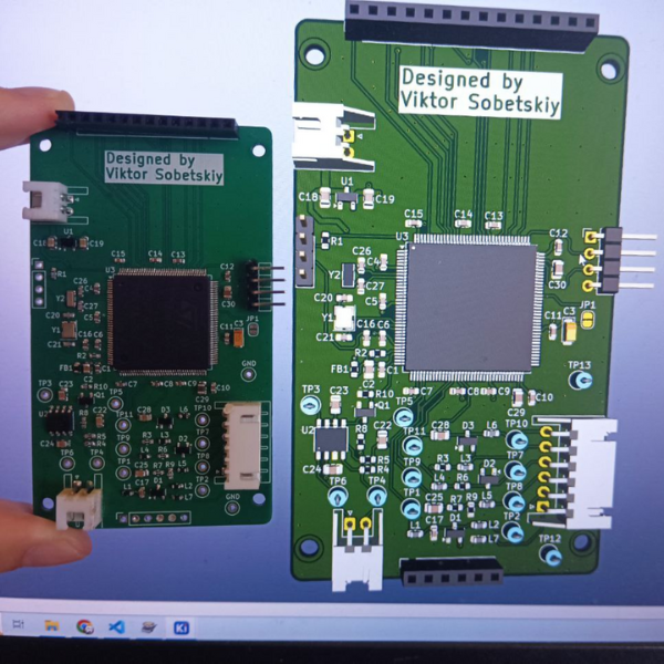
This project has been a valuable learning experience, despite the challenges faced. Further work is required to resolve the signal distortion issue and improve the overall performance of the metal detector.
| Qty | Value | Footprint | References |
|---|---|---|---|
| 14 | 100nF | Capacitor_SMD:C_0603_1608Metric | C1, C4, C5, C6, C7, C8, C9, C10, C11, C12, C13, C14, C15, C16 |
| 13 | TestPoint | TestPoint:TestPoint_Loop_D1.80mm_Drill1.0mm_Beaded | TP1, TP2, TP3, TP4, TP5, TP6, TP7, TP8, TP9, TP10, TP11, TP12, TP13 |
| 8 | 1uF | Capacitor_SMD:C_0805_2012Metric | C2, C18, C19, C22, C23, C24, C25, C28 |
| 7 | 15uH | Inductor_SMD:L_0603_1608Metric | L1, L2, L3, L4, L5, L6, L7 |
| 4 | 100R | Resistor_SMD:R_0603_1608Metric | R2, R3, R6, R7 |
| 4 | 12pF | Capacitor_SMD:C_0603_1608Metric | C20, C21, C26, C27 |
| 4 | MountingHole | MountingHole:MountingHole_2.7mm_M2.5_ISO7380 | H1, H2, H3, H4 |
| 3 | 47K | Resistor_SMD:R_0603_1608Metric | R4, R8, R10 |
| 3 | MMBD7000 | Package_TO_SOT_SMD:SOT-23 | D1, D2, D3 |
| 2 | 10K | Resistor_SMD:R_0603_1608Metric | R1, R5 |
| 2 | 2.2uF | Capacitor_SMD:C_0805_2012Metric | C29, C30 |
| 1 | 2.2R | Resistor_SMD:R_0603_1608Metric | R9 |
| 1 | 32.768kHz | Crystal:Crystal_SMD_3215-2Pin_3.2x1.5mm | Y2 |
| 1 | 4.7uF | Capacitor_Tantalum_SMD:CP_EIA-3216-18_Kemet-A | C3 |
| 1 | 47nF | Capacitor_SMD:C_0603_1608Metric | C17 |
| 1 | 600R_100MHz | Resistor_SMD:R_0603_1608Metric | FB1 |
| 1 | 8002 | lib:SOIC8 | U2 |
| 1 | AO3402 | Package_TO_SOT_SMD:SOT-23 | Q1 |
| 1 | Conn_01x02_Socket | Connector_JST:JST_XH_S2B-XH-A_1x02_P2.50mm_Horizontal | J4 |
| 1 | Conn_01x02_Socket | Connector_JST:JST_XH_S2B-XH-A-1_1x02_P2.50mm_Horizontal | J2 |
| 1 | Conn_01x04_Pin | Connector_PinHeader_2.54mm:PinHeader_1x04_P2.54mm_Vertical | J6 |
| 1 | Conn_01x04_Pin | Connector_PinHeader_2.54mm:PinHeader_1x04_P2.54mm_Horizontal | J7 |
| 1 | Conn_01x04_Socket | Connector_PinSocket_2.54mm:PinSocket_1x06_P2.54mm_Vertical | J5 |
| 1 | Conn_01x06_Socket | Connector_JST:JST_XH_S6B-XH-A_1x06_P2.50mm_Horizontal | J3 |
| 1 | Conn_01x14_Socket | Connector_PinSocket_2.54mm:PinSocket_1x14_P2.54mm_Vertical | J1 |
| 1 | Crystal_GND24 | Crystal:Crystal_SMD_3225-4Pin_3.2x2.5mm | Y1 |
| 1 | MCP1700x-330xxTT | Package_TO_SOT_SMD:SOT-23 | U1 |
| 1 | STM32H723ZGTx | Package_QFP:LQFP-144_20x20mm_P0.5mm | U3 |
| 1 | SolderJumper_2_Open | Jumper:SolderJumper-2_P1.3mm_Open_RoundedPad1.0x1.5mm | JP1 |
It measures 50 × 86 mm and has 4 copper layers, 1.6 mm thick.
82 parts, built around the MMBD7000 and AO3402. The full list of its parts is on this page, with links to each part's symbol and footprint where PCBKit's library has them.
From the tor1kk/rockmd repository on GitHub, at the commit this page was made from: the board is hardware/metal_detector_prototype.kicad_pcb and its schematic hardware/metal_detector_prototype.kicad_sch. PCBKit opens the board in the browser, with nothing to install.
Its repository publishes it under the GPL-3.0 licence: you may reuse it on that licence's terms (keep the author's notice, and for a copyleft licence share your changes alike).
edgranzella/PTuP_2026_displayLCD_8Zonas_4Salidas
Este repositorio contiene el diseño electrónico y ruteado de PCB avanzado desarrollado en KiCad para el módulo PTuP 2026.


ebrithiljonas/OMG_PCB
All in One PCB for the OpenMQTTGateway Project

Prototype-Fund-Hardware/MYND-Hardware
Inofficial hardware repository for the Teufel MYND loudspeaker: https://teufel.de/mynd-107002004


daisuke-ym/micro-mouse
[^1]: Unistep2 ライブラリを用いてほぼ最高速度で回しても約15rpmなので、 1区画進むのに約4秒かかります。 大会では16x16区画、256区画あるので、全探索するのに15分以上かかるため、 偶然を除いて競技時間10分以内に完走することは不可能です。