
2 layers96.8 × 97 mm
Psoc5power
profdc9/DRSSTC-PCB-Pack
A pack of PCBs for a dual resonant solid state tesla coil setup. Pretty much everything you need.
133 parts59

 ToneAlchemy/BiasPro16
A professional-grade, dual-probe Arduino Bias Meter for guitar tube amplifiers. Open source hardware & firmware
BiasPro InputProtection v3 is an open-source printed circuit board by ToneAlchemy, from the ToneAlchemy/BiasPro repository on GitHub, published under the MIT licence. It is a 2-layer board of 33.9 × 90 mm with 18 parts on 35 nets, routed with 86 tracks and 0 vias.
It is built around the ADS1115 and 1N4733A. Its parts include 3 switches and 1 IC. It belongs with the audio and music and sensors and measurement boards of this library.
This repository contains the complete, mathematically hardened firmware for a professional-grade, dual-probe vacuum tube BiasPro. Designed for guitar amplifier technicians, this tool provides real-time, high-resolution measurements of Plate Voltage, Cathode Current, and True Plate Dissipation (Watts & %) for power tubes (e.g., 6L6GC, EL34, 6V6, KT88).
This firmware was completely re-architected from scratch using modern, memory-safe embedded C++ principles to eliminate dynamic memory leaks and ensure rock-solid physical safety lockouts.
Current firmware version: v1.1.1 — see CHANGE_LOG.md for the full change history. Highlights since v1.0.0: a vertically stacked, horizontally centered layout on the Tube Select and Profile Manager screens (with improved line spacing for clear reading), a Hold LEFT shortcut to escape the Profile Manager directly to Tube Select, a live plate-voltage readout on the Calibration screen (match it to your DMM as you adjust), sensor-glitch rejection so a noisy ADC read can't false-release the lockout or flash 0 V, profile-store protection so a bad edit can't wipe your saved tube profiles, and a flicker-free VOLTAGE LOCKOUT screen.
| 1. Splash Screen | 2. Tube Select | 3. Live Bias Mode |
|---|---|---|
 | 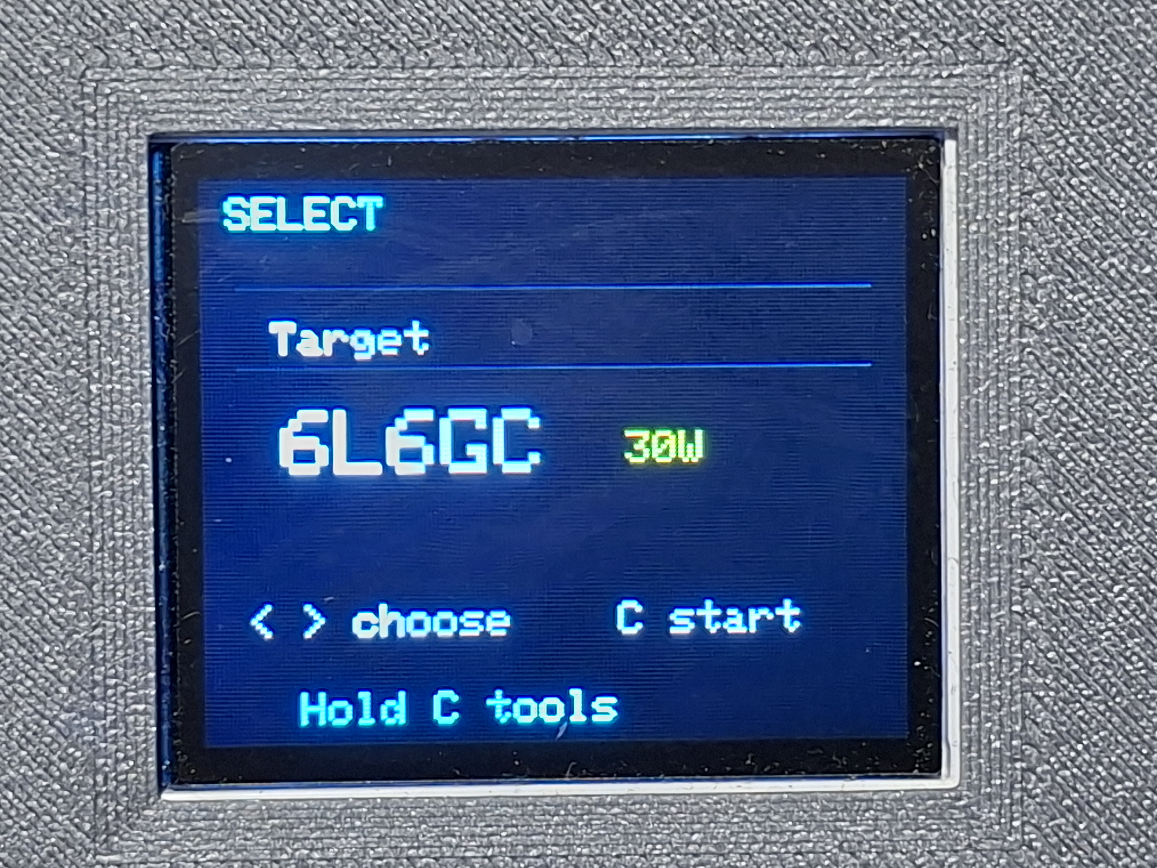 | 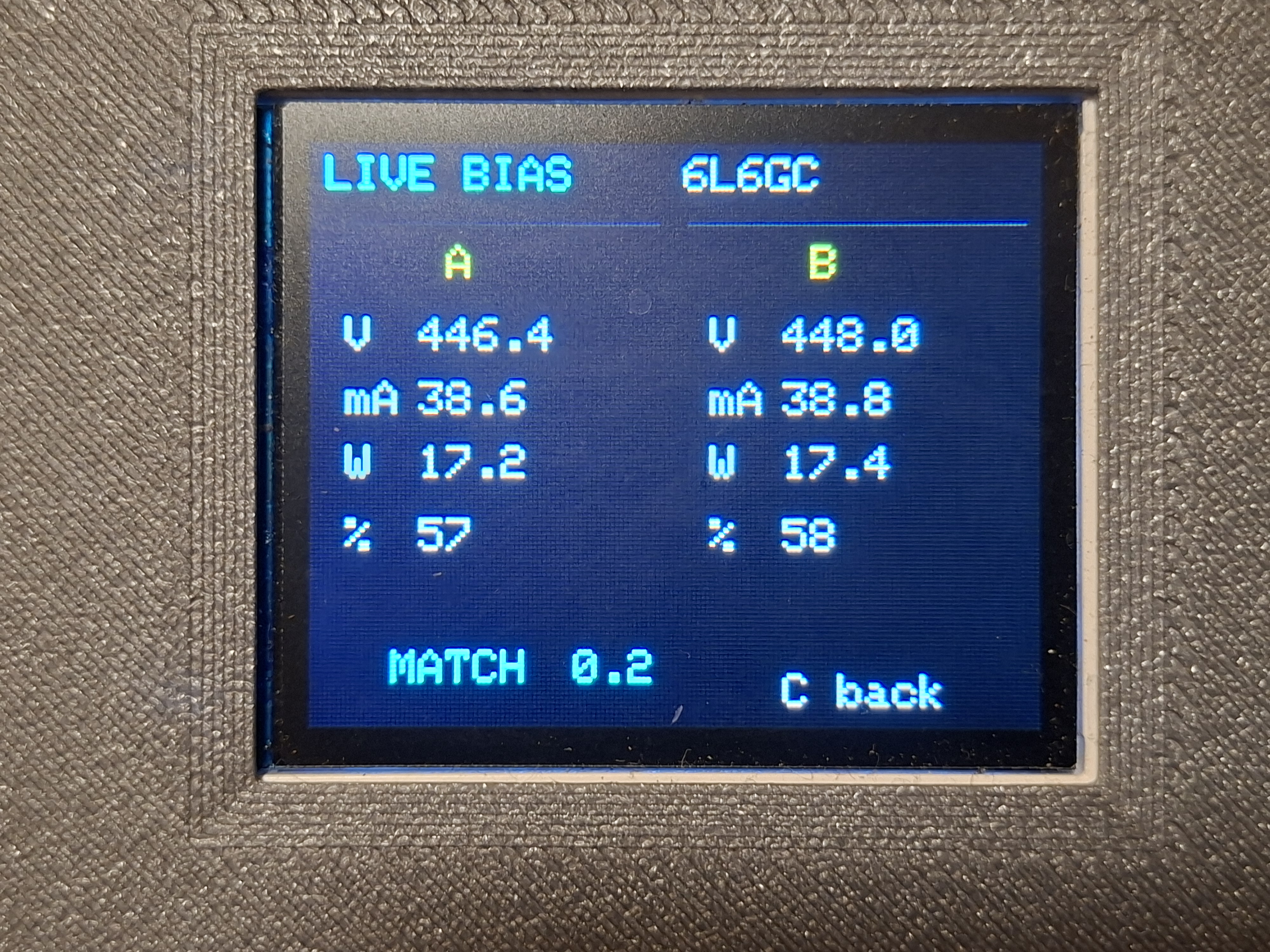 |
| 4. Calibration | 5. Profiles Manager | 6. Profile Edit |
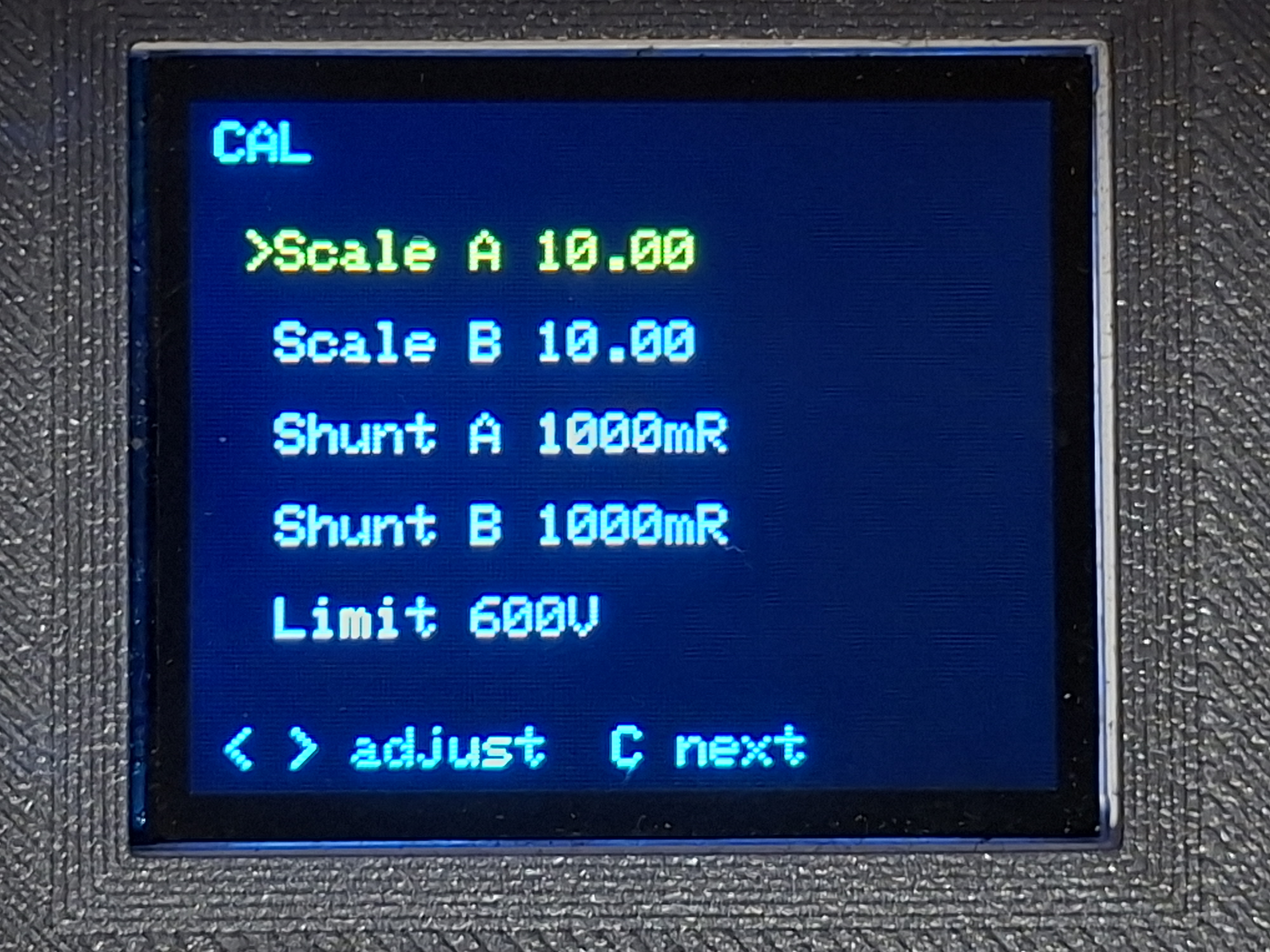 | 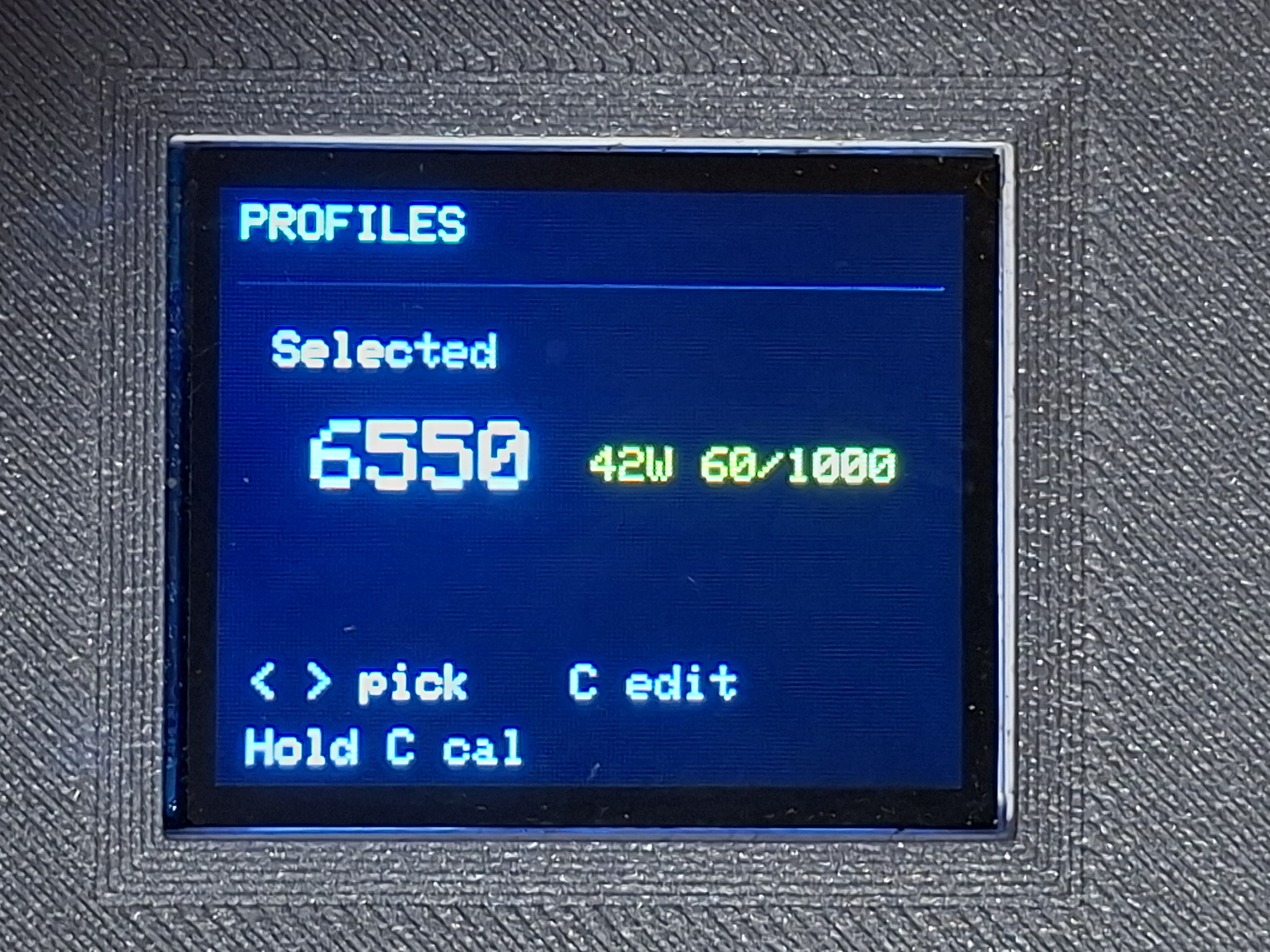 | 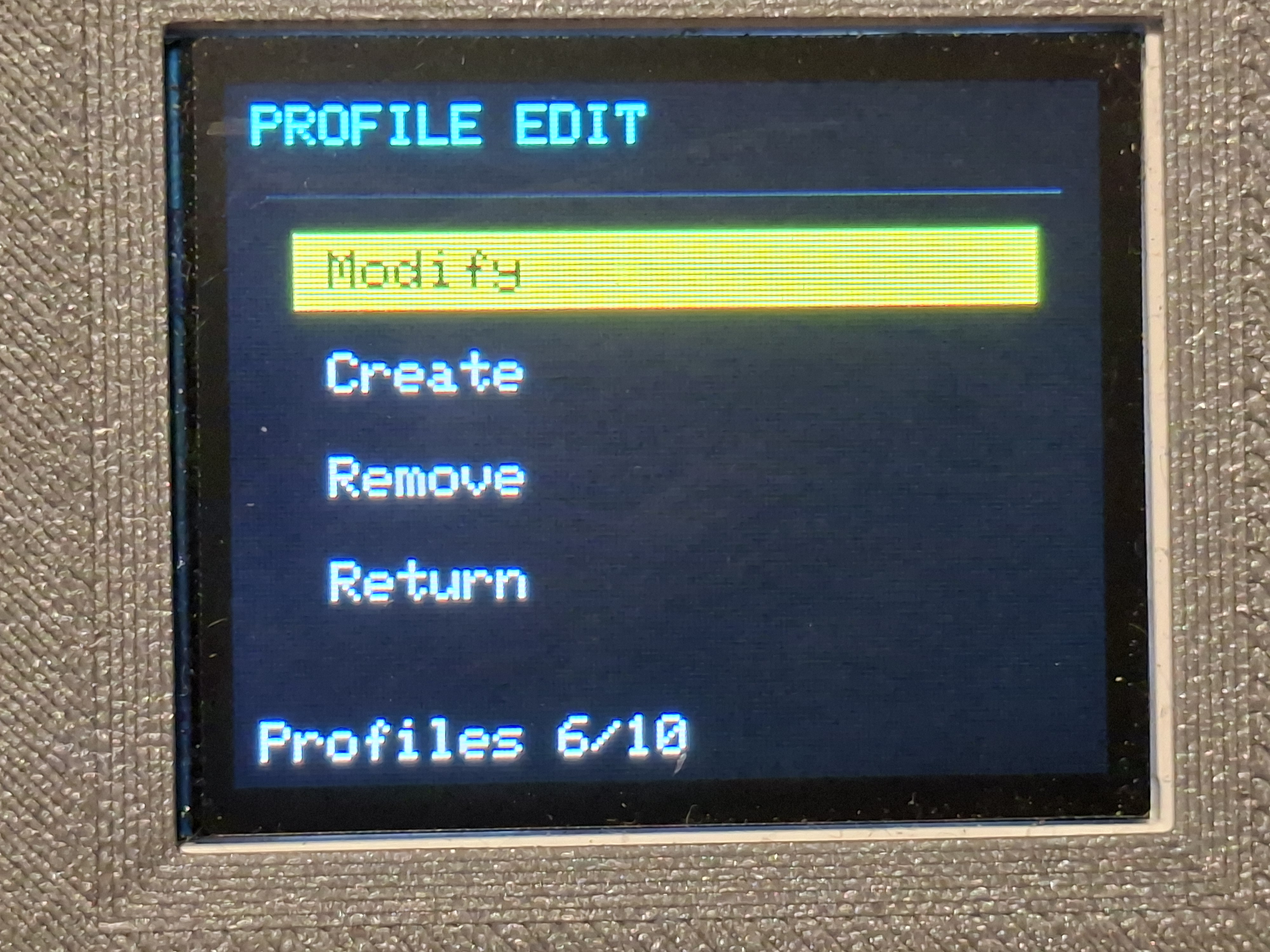 |
| 7. EDIT PROFILE | 8. BiasPro Enclosure | 9. BiasPro - Setup |
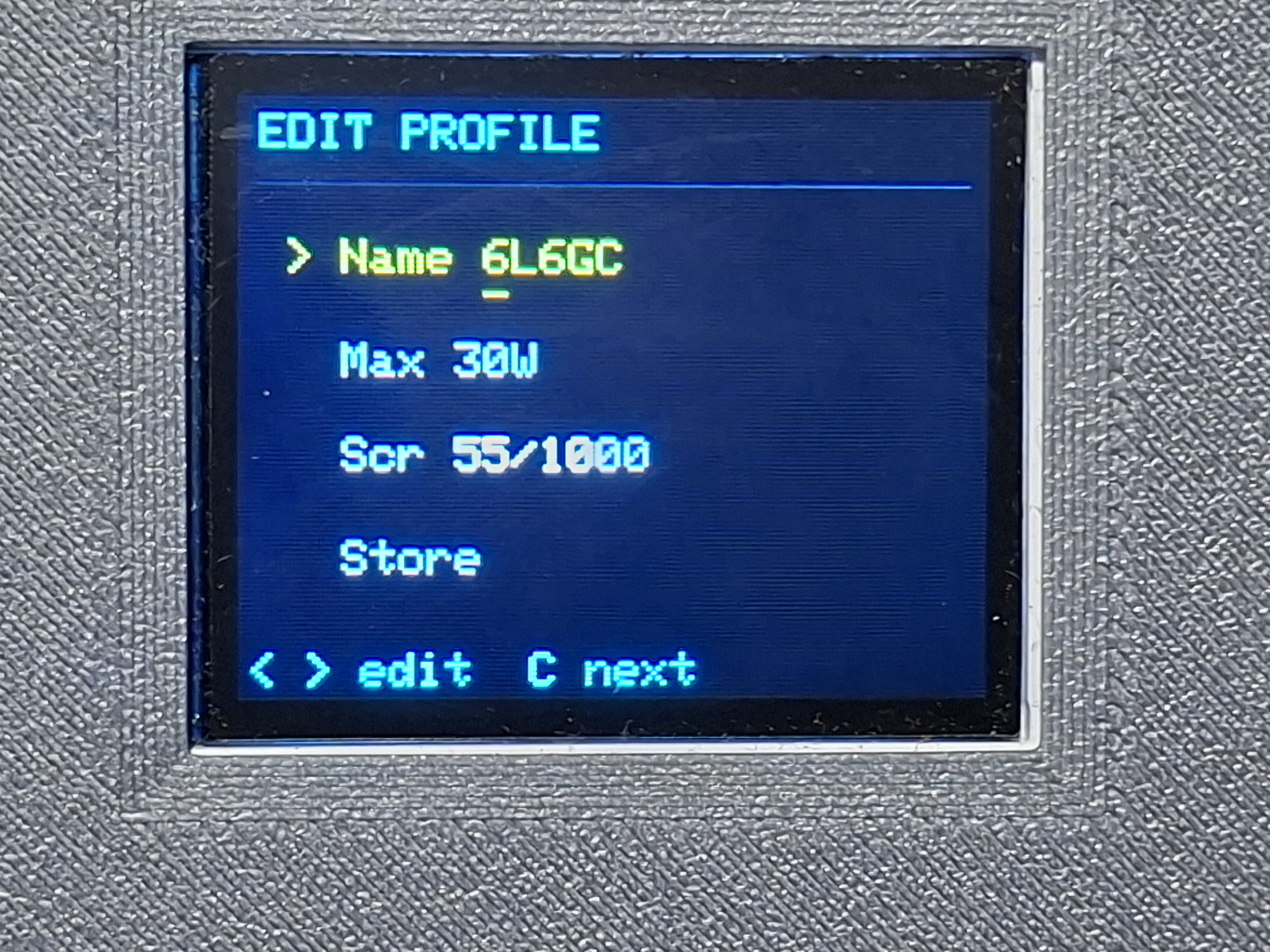 | 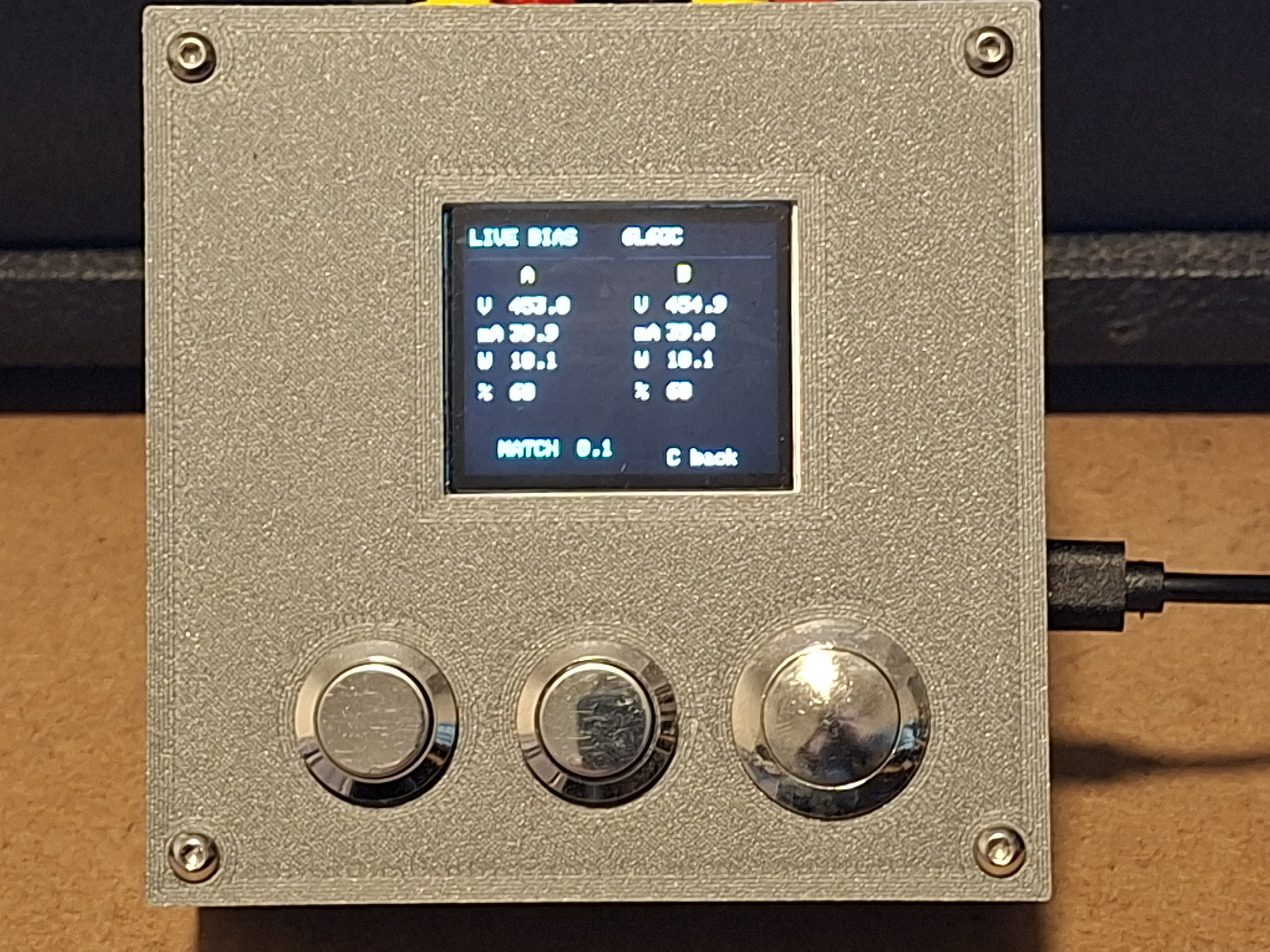 | 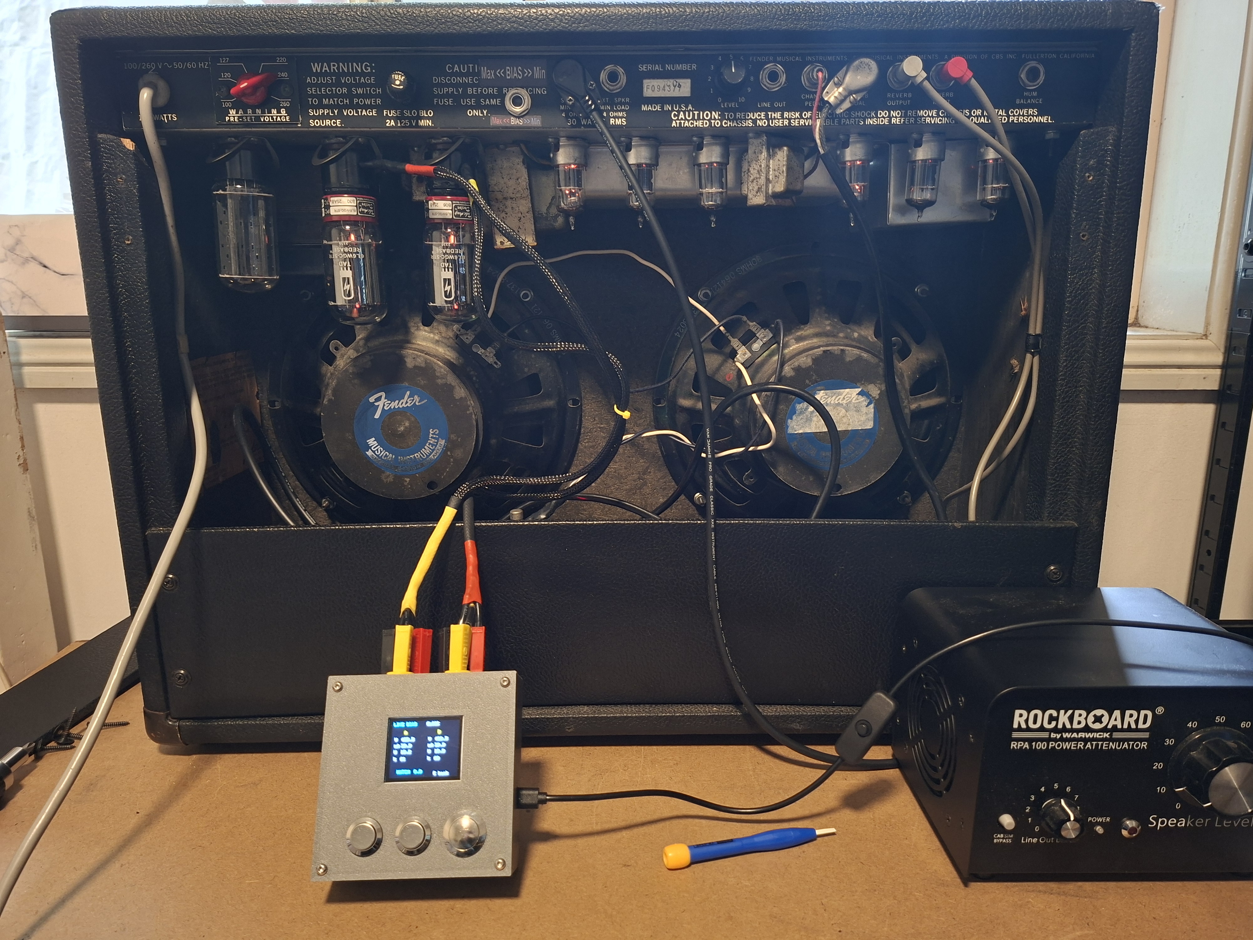 |
LETHAL VOLTAGES ARE PRESENT IN TUBE AMPLIFIERS.
Tube amplifiers store lethal voltages in their filter capacitors even after being unplugged. This firmware is only a measurement tool; it cannot make unsafe wiring or handling safe.
[!CAUTION]
⚠️ WARNING: HIGH VOLTAGE SAFETY
Tube amplifiers contain lethal high voltage (often 400V–500V+), even when powered off and unplugged.
This project involves building and using test equipment that interfaces directly with these dangerous circuits.
- Risk of Death: Incorrect wiring of the bias probes or misuse of this device can expose you to lethal current.
- Filter Capacitors: High voltage can remain stored in the amplifier's capacitors long after the power is cut. You must know how to safely drain filter capacitors before opening any chassis.
- Qualified Personnel Only: If you are not trained in high-voltage safety or are uncomfortable working with live circuits, do not build or use this device. Take your amplifier to a qualified technician instead.
DISCLAIMER & NO SUPPORT: This project is provided "as is" with no warranty and no technical support. The author cannot provide assistance with assembly, troubleshooting, or code modifications. The author assumes no liability for injury, death, or equipment damage resulting from the use or construction of this device. Use entirely at your own risk.
[!IMPORTANT]
⚡ Critical Safety: Capacitor Discharge
Before touching any internal component or connecting probes to a chassis, you must verify the filter capacitors are drained.
- The Golden Rule: Always measure with a multimeter to confirm 0VDC before touching anything.
- Discharge Tool: Do not rely on the amp to drain itself. Use a dedicated Capacitor Discharge Tool to safely bleed off voltage.
- DIY Tip: You can build one using a high-wattage resistor (e.g., 2kΩ to 5kΩ, 5 Watts) wired to a probe and an alligator clip for ground. This slows the discharge and prevents sparking, unlike a screwdriver short.
- One-Hand Rule: When working on live amps, keep one hand in your pocket to prevent current from passing across your chest/heart.
[!NOTE]
🛡️ Recommended Safety Gear
If you are working inside a live amplifier chassis, we strongly recommend using the following safety equipment:
- Isolation Transformer: This isolates the amplifier from the mains earth ground, significantly reducing the risk of lethal shock if you accidentally touch a live component while grounded.
- Dim Bulb Limiter (Current Limiter): Essential when powering up an amplifier for the first time after a repair. It prevents catastrophic damage (blown transformers) if there is a short circuit.
- ⚠️ CRITICAL WARNING: Do NOT attempt to set the final bias while running through a Dim Bulb Limiter. The limiter drops the wall voltage, which lowers the plate voltage and gives false low bias readings. Always bypass the limiter for the final precision bias adjustment.
- Variac (Variable Transformer): Highly recommended for two purposes:
- Voltage Stabilization: Wall voltage fluctuates. A Variac allows you to set the input voltage exactly to your country's standard (e.g., 240V in Australia, 120V in USA, 230V in UK). This ensures your bias readings are accurate and consistent, rather than drifting with high/low wall voltage.
- Soft Start / Reforming: Useful for slowly bringing up the voltage on vintage amplifiers to reform old capacitors safely.
[!TIP] New to Biasing? Check out our dedicated guide:
📖 Read the Step-by-Step Biasing Guide
Learn how to safely bias Fender Prosonic & Fixed-Bias Amps.
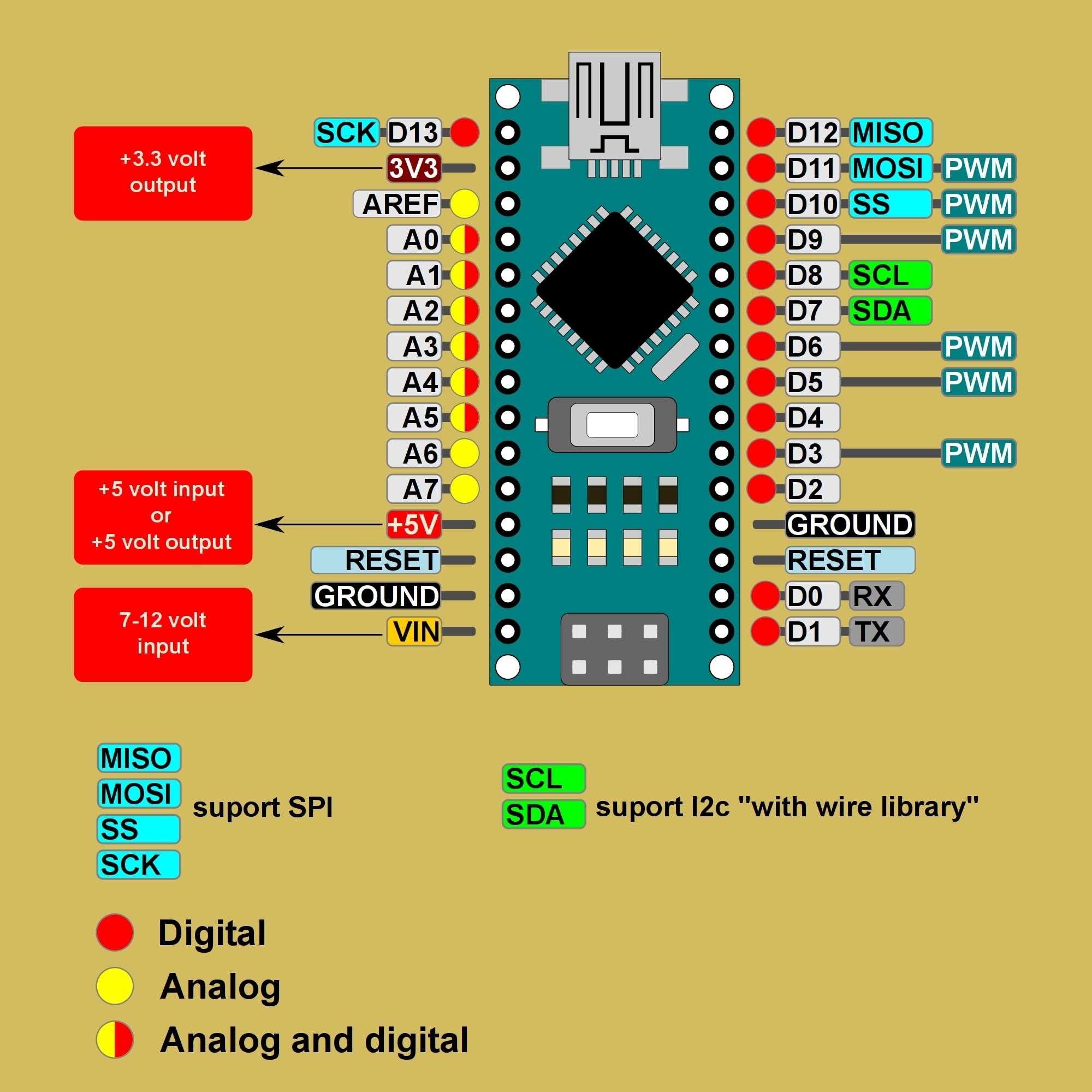
0x48| Function | Arduino Nano Pin |
|---|---|
| TFT SCLK/SCL | D13 |
| TFT MOSI/SDA | D11 |
| TFT CS | D10 |
| TFT DC | D9 |
| TFT RST | D8 |
| Button Center | D7 (Uses INPUT_PULLUP) |
| Button Right | D6 (Uses INPUT_PULLUP) |
| Button Left | D5 (Uses INPUT_PULLUP) |
| ADS1115 SDA | A4 |
| ADS1115 SCL | A5 |
When sourcing displays for BiasPro, you will encounter two primary hardware paths: the official Adafruit breakout or generic clone modules. Understanding their electrical architecture is essential for proper wiring and long display life:
| Feature | Adafruit 1.8" TFT Breakout (PID 358) | Generic Clone Module (Driver IC: ST7735S / NOMEN_TEC) |
|---|---|---|
| Driver IC | ST7735R | Usually ST7735S |
| Onboard 3.3V LDO Regulator | ✅ Yes (ultra-low-dropout 3.3V regulator) | ⚠️ Usually present (662K), but verify U1 & J1 |
| Onboard Logic Level Shifter | ✅ Yes (active CD74HC4050 buffer IC) | ❌ None (pins route straight to glass ribbon) |
| 5V Supply Compatibility | ✅ Yes (accepts 3.3V – 5V on VCC) | ✅ Yes (if U1 is populated and J1 is open) |
| 5V Logic Compatibility | ✅ Native 5V plug-and-play | ⚠️ Requires 1kΩ to 1.5kΩ series resistors on SPI/control lines |
| Header Pin Labels | LITE, MISO, SCK, MOSI, TFT_CS, CARD_CS, D/C, RESET, VCC, Gnd | GND, VCC/VDD, SCL, SDA, RES/RST, DC, CS, BL/BLK |
[!NOTE] Important Distinction on Adafruit PID 358 vs. PID 618:
The official recommended reference part is the Adafruit PID 358 assembled breakout (which includes the mounting PCB, microSD slot, 3.3V regulator, and CD74HC4050 level shifter).
In contrast, Adafruit PID 618 is the raw, unmounted 1.8" TFT panel only (flexible ribbon cable, no PCB). PID 618 is strictly 3.3V-only and requires external regulation and level shifting when paired with a 5V Arduino Nano.
The BiasPro_InputProtection_v3 PCB routes the global 5V rail directly to Pin 8 (VCC) of the display header, and routes digital pins D8, D9, D10, D11, and D13 straight to the display's SPI control lines without inline resistor pads. Review the configuration requirements for your specific display:
The reference hardware design targets the Adafruit PID 358 assembled breakout natively:
VCC to Arduino Nano 5V (or 3.3V; the onboard regulator safely handles 3.3V–5V input) and GND to Arduino GND.D13 → Adafruit SCKD11 → Adafruit MOSID10 → Adafruit TFT_CSD9 → Adafruit D/CD8 → Adafruit RESETLITE to 3V3 or 5V (or to an Arduino PWM pin if software brightness control is desired).CARD_CS and MISO belong to the onboard microSD card socket and remain unconnected in BiasPro.tft.initR(INITR_18BLACKTAB) via the Adafruit_ST7735 library, targeting the PID 358 natively.Budget 8-pin breakout modules (frequently marked Driver IC: ST7735S or NOMEN_TEC V2.0) run on native 3.3V silicon and lack active logic-level translation buffers.
U1 & J1 Check):
662K (or AMS1117-3.3) at footprint U1, alongside an unbridged solder jumper J1.U1 is populated and J1 is open, feeding 5V into VCC is completely safe (the regulator steps 5V down to 3.3V for internal panel power).U1 is unpopulated and J1 is bridged, the module is strictly 3.3V-only. Connecting 5V to VCC will destroy the panel.D13 → [1kΩ Resistor] → Display SCL / SCKD11 → [1kΩ Resistor] → Display SDA / MOSID10 → [1kΩ Resistor] → Display CSD9 → [1kΩ Resistor] → Display DC / A0D8 → [1kΩ Resistor] → Display RES / RESETBiasPro_InputProtection_v3 PCB routes the Nano directly to the display header without inline resistor pads, builders opting for series resistors should wire the clone module off-board or install inline resistors along the wiring harness rather than soldering the display directly flush into the PCB header.BL / BLK): The onboard transistor (Q1 / J3Y) and base resistor handle switching. Connect BL to the Nano's 3V3 pin, or to an Arduino GPIO pin through a 1kΩ resistor if software dimming is desired.To guarantee a successful compile, you must use these exact library versions in the Arduino IDE:
Adafruit GFX Library v1.12.5Adafruit ST7735 and ST7789 Library v1.11.0Adafruit BusIO v1.17.4The firmware compiles to approximately 30,626 bytes of program storage. This is a very tight fit on older hardware, but it will successfully flash to both new and old Arduino Nanos.
Newer Arduino Nano (Standard Bootloader): If you have a newer official Nano or a high-quality modern clone, use the Processor: ATmega328P setting in the Arduino IDE. These boards use the modern Optiboot bootloader, which leaves 32,256 bytes of usable flash space. The firmware will fit easily with roughly 1.6KB to spare.
Older Arduino Nano & Generic Clones (Old Bootloader): Many cheaper clones and older Nanos use the legacy bootloader, which takes up more space and leaves exactly 30,720 bytes of usable flash space. The firmware will still successfully flash using the Processor: ATmega328P (Old Bootloader) setting, fitting with roughly 94 bytes to spare:
Sketch uses 30626 bytes (99%) of program storage space. Maximum is 30720 bytes.
Global variables use 750 bytes (36%) of dynamic memory, leaving 1298 bytes for local variables. Maximum is 2048 bytes.
It works perfectly, but you have very little room to add additional features or text without overflowing the memory.
Need more space on an old Nano? You can manually upgrade an old Nano to the modern Optiboot bootloader using an ISP programmer. Once upgraded, you simply change your board selection in the Arduino IDE to "Arduino Uno" to unlock the extra 1.5KB of flash space.
Tube amplifiers are electrically noisy environments. High voltage spikes, flyback EMF, or loose tube socket connections can create strong Electromagnetic Interference (EMI) that can lock up the internal I2C bus connecting the Arduino to the ADS1115 ADC.
To protect against these EMP-like events, this firmware completely bypasses the standard Adafruit ADC library and manually writes to the I2C registers. More importantly, it utilizes the modern Wire.setWireTimeout(25000, true) feature.
How it works: If the I2C bus freezes due to interference, the system detects the hang within 25 milliseconds, automatically resets the I2C hardware pins, and immediately resumes reading the Bias probes without ever rebooting the Arduino or losing your place on the screen.
Why no Hardware Watchdog Timer (WDT)? Older versions of this project used the hardware WDT. However, a severe silicon bug in common LGT8F328P Arduino Nano clones caused the WDT to trigger infinite boot-loop crashes during UI updates. The software-level Wire timeout is infinitely more reliable, handles EMI elegantly, and completely avoids these bootloader bugs.
In addition to the software timeout recovery, the physical BiasPro hardware reinforces the ADS1115 I²C bus with auxiliary pull-up resistors:
SDA $\rightarrow$ 4.7kΩ $\rightarrow$ VDDSCL $\rightarrow$ 4.7kΩ $\rightarrow$ VDDThese $4.7\text{ k}\Omega$ metal-film resistors were added during live amplifier testing to strengthen the I²C bus against EMI-induced corruption and bus lockups in electrically aggressive valve-amplifier environments. By lowering the bus impedance and sharpening the $SDA$/$SCL$ rising edges, the bus becomes significantly more immune to capacitively coupled noise from high-voltage plate leads and transformer fields.
Many common ADS1115 breakout modules already include $10\text{ k}\Omega$ onboard pull-up resistors. Adding external $4.7\text{ k}\Omega$ resistors places them in parallel, resulting in an effective bus pull-up impedance of approximately $\approx 3.2\text{ k}\Omega$ (drawing only $\approx 1.56\text{ mA}$ sink current at 5V, comfortably within the $3\text{ mA}$ I²C standard limit). These hardware pull-ups work synergistically with the firmware’s Wire.setWireTimeout mechanism to deliver rock-solid stability.
If you are unable to upload the firmware and see an error like stk500_recv(): programmer is not responding:
The Cause: You are likely using an older Arduino Nano (or a generic clone) that uses the legacy bootloader.
The Fix: In the Arduino IDE, go to Tools > Processor and change the setting from "ATmega328P" to "ATmega328P (Old Bootloader)". Then try uploading again.
Note: Newer official Nanos (and USB-C versions) usually use the standard "ATmega328P" setting.
Some older Arduino Nano boards (and many low-cost clones) came with an outdated "Bootloader" that had a bug preventing the chip from recovering correctly after a hardware Watchdog Reset.
Wire.setWireTimeout bus reset. You should no longer experience infinite boot loops when encountering EMI. If you do, ensure you have correctly installed the Wire library updates in the Arduino IDE.If your display lights up but shows static, garbage pixels, or wrong colors:
The Cause: You likely have a "Green Tab" or "Red Tab" clone display. The plastic tab on the screen protector often indicates the internal driver version.
The Fix: Open the firmware source code (DisplayManager.cpp or main .ino configuration) and find the initialization line: tft.initR(INITR_18BLACKTAB);
Change it to one of the following and re-upload until the screen looks correct:
tft.initR(INITR_18GREENTAB);tft.initR(INITR_18REDTAB);If you notice the onboard yellow/orange L LED on your Arduino Nano flickering continuously while the device is running:
L LED is hardwired directly to digital pin D13.D13 serves as the high-speed SPI Clock (TftSclkPin). Every time the live bias values update (multiple times per second), thousands of SPI clock pulses toggle D13 at high frequency.L LED effectively functions as a live hardware activity monitor showing active SPI communication between the ATmega328P and the display.This project is written as a standard Arduino sketch (.ino) and was developed using the official Arduino IDE.
Recommended Method: We strongly recommend using the Arduino IDE for the easiest setup. Its built-in Library Manager (Tools > Manage Libraries) makes it simple to install the required dependencies (e.g., Adafruit GFX) without complex manual configuration.
Alternative IDEs: Advanced users can compile this code in other environments, such as Visual Studio Code (with PlatformIO) or Microchip Studio. However, please note that you will need to manually manage library paths and dependencies.
📥 Download Official Arduino IDE: Download Official Arduino IDE
The pure calculation and storage logic (bias math, probe classification, EEPROM
checksums/validation, and the over-voltage protection state machine) lives in
Arduino-independent units (MathCalculations, ProtectionSystem, StorageCore)
so it can be verified on a PC with any C++17 compiler — no board required. The
host tests link the actual firmware sources, not a copy, so they cannot drift
from what ships.
# From the repository root, with g++ (or clang++):
g++ -std=c++17 -I BiasPro test/host_calculation_tests.cpp \
    BiasPro/MathCalculations.cpp BiasPro/ProtectionSystem.cpp \
    BiasPro/StorageCore.cpp -o biaspro_host_tests
./biaspro_host_tests        # expect: "host calculation tests passed"
A second, source-level UI regression check (PowerShell) asserts that the display code keeps using its incremental-redraw pattern and that the safety-screen routing stays intact:
powershell -ExecutionPolicy Bypass -File test/screen_redraw_static_check.ps1BiasPro introduces professional-grade data integrity and safety features not found in standard DIY alternatives.
Dual Probe Measurement: Simultaneous real-time monitoring of Tube A and Tube B.
True Plate Dissipation: Calculates power (Watts) and dissipation percentage based on the specific tube type.
Screen Current Correction: Implements industry-standard math to subtract estimated screen current, ensuring the displayed bias represents true Plate dissipation, not just Cathode current.
Checksum Protection: The EEPROM data includes a computed checksum. If the memory is corrupted or a new chip is installed, the system detects the error and automatically restores safe default values, preventing dangerous behavior.
Safety Clamps: The Calibration Menu now prevents users from accidentally setting dangerous values (e.g., setting a shunt resistor to 0.0Ω or a voltage scaler to 0), effectively "clamping" entries to safe, realistic ranges.
Profile Store Protection: Your custom tube profiles are validated on both save and load. A malformed entry (for example a blank name) is rejected rather than written, so a bad edit can never silently wipe your saved profiles back to defaults on the next power-up.
Active Over-Voltage Monitor: While in Live Bias mode, the plate voltage is checked on every measurement cycle; if it exceeds the configured limit the interface locks and displays a red "LOCKOUT" warning until the voltage falls back into the safe band. (The lock, once tripped, persists across screens until released.) This automatic check runs only in Live Bias mode — it is not active on the Calibration screen, even though that screen shows a live voltage. During calibration, rely on your DMM and your own judgement (see the Calibration Guide warning below).
Safety Hysteresis: The system requires a voltage drop of 50V (hysteresis) before resetting the safety lock, preventing rapid toggling near the limit.
Input Debouncing: Advanced state-machine logic eliminates switch "recoil" and bounce, ensuring the cursor never jumps unintentionally.
Sensor-Glitch Rejection: A failed or corrupted ADC read (for example from an EMI burst) is flagged invalid rather than trusted. An invalid reading can never release an active voltage lockout, and Live Bias mode holds the last good measurement instead of momentarily flashing 0 V.
Flicker-Free Display: Every screen — including the red VOLTAGE LOCKOUT alert — uses incremental redraw, so critical readouts stay rock-steady instead of strobing.
Centered, Stacked UI Layout: Selection screens (Tube Select and Profile Manager) feature vertically stacked, horizontally centered text elements with balanced line spacing for improved readability.
Software Calibration: Shunt resistance and Voltage Divider scaling can be adjusted via the screen menu and saved to EEPROM. You do not need to edit the source code to calibrate the unit. Edits save automatically when you advance to the next field or leave the screen — there is no separate "save" step — which also minimises wear on the EEPROM.
Live Voltage Feedback: While adjusting the Scale or Shunt fields in Calibration mode, the screen displays a live, non-blocking computed plate voltage (refreshed every ~350 ms) for the active probe. This allows you to match the calibration to your DMM readings in real time.
For those interested in the engineering, here is how the BiasPro safely measures high-voltage tube amplifiers.
The Arduino cannot measure 500V directly, and the ADS1115 is configured with a high-resolution Programmable Gain Amplifier (PGA) range of ±0.256V (256 mV) to maximize measurement accuracy.
To measure current, we use Ohm's Law (V = I × R).
The Circuit: The tube's cathode current flows through a precision 1Ω Shunt Resistor to ground.
The Measurement: The current flowing through the resistor creates a tiny voltage drop across it (e.g., 35mA of current creates 35mV).
The ADC: The high-precision ADS1115 ADC measures this tiny voltage drop with extreme accuracy. The Arduino then converts that millivolt reading directly into milliamps (since 1mV = 1mA across a 1Ω resistor).
Once the system knows the Voltage (V) and the Current (I), it calculates the Plate Dissipation in real-time.
Formula: Watts = Plate Voltage × Plate Current
Screen Correction: If enabled, the system first subtracts the estimated Screen Current from the total current to ensure the Wattage displayed is for the Plate only, providing the most accurate bias reading possible.
| Quantity | Component | Description |
|---|---|---|
| 1 | Arduino Nano (Recommended: USB-C Version) | Microcontroller board (ATmega328P) |
| 1 | Adafruit ST7735 1.8" TFT | 160x128 Color TFT Display (SPI) |
| 1 | ADS1115 16-Bit ADC Module | High-precision 4-channel ADC (I2C) |
| 3 | Tactile Push Buttons | Menu navigation (Left, Right, Center/Select) |
| 1 | Project Enclosure | 3D printed case (See below) |
| - | Hook-up Wire | 22 AWG for internals |
| 2 | Bias Probes | Octal (8-pin) probes (e.g., TubeDepot Bias Scout or DIY) |
Before sourcing parts, please review these critical hardware constraints to ensure your build works correctly.
⚠️ CRITICAL: You MUST use the ADS1115 (16-Bit) ADC module.
Do NOT use the ADS1015: This is a cheaper, 12-bit version that looks identical.
The Issue: The firmware uses a specific multiplier (0.0078125 mV/bit) calculated for 16-bit resolution. If you use an ADS1015, your bias readings will be incorrect by a factor of 16.
Required: Adafruit ST7735 1.8" Color TFT (or compatible).
Not Supported: This firmware is NOT compatible with monochrome OLED displays (SSD1306 or SH1106) used in other versions.
Supported: Isolated USB Wall Charger or 9V Battery.
Not Supported: Do NOT attempt to power this unit directly from the amplifier's 6.3V AC heater lines.
The Risk: This hardware revision does not include the necessary rectification circuitry. Connecting heater lines to the Arduino will destroy the unit.
Clarification: Even if you plug the amplifier into an Isolation Transformer, it is STILL UNSAFE to connect the BiasPro's USB port to a computer while probing.
The Physics: Most isolation transformers pass the Earth Ground pin straight through. This means the Ground Loop danger persists. Never connect USB to a PC while the probes are in an amp. If you do so, you do it at your own risk!
We highly recommend the Tube Depot Bias Scout Kit for your hardware. It provides a professional, safe, and robust enclosure for the socket and resistor.
Product Link: Tube Depot Bias Scout Kit
Assembly Manual: Download PDF Instructions
Assembly Notes for this Project:
The Resistor: The kit includes a 1Ω 1W resistor. This is perfect for this project and matches the default calibration (1.00Ω).
Wiring Colors: If you follow the standard instructions, the output plugs will match this project's wiring guide:
V_IN via voltage divider).GND).ADC_IN).Connection: You can either cut the banana plugs off and wire them directly to your PCB/Enclosure, or install female banana jacks on your BiasPro enclosure for a detachable probe.
While we recommend the Tube Depot Bias Scout Kit for the easiest assembly, you can build your own probes using the Bias Scout Kit Instructions with standard components.
To build one probe, you will need:
[!NOTE] The Hoffman Amps Bias Checker probe design will NOT work with this project. That probe only measures Cathode Current. This project requires probes that measure both Plate Voltage and Cathode Current.
A custom enclosure has been designed to house the Arduino Nano, Display, and Buttons safely.
Design Platform: TinkerCAD
Editable Source: BiasPro Enclosure V11 Files (Note: You must be logged into Tinkercad to access this link)
Ready-to-Print Files: BiasPro_Enclosure_STL
Printing Notes:
You can export the .STL files directly from the link above. Standard PLA or PETG is suitable for this project. The case is designed to keep the low-voltage electronics isolated and secure.
For a cleaner build and enhanced reliability, a custom PCB has been designed to replace hand-wiring. This board hosts the Arduino Nano, ADS1115, and input connectors.
Hardware Input Protection: The board includes 1N4733A Zener Diodes (5.1V) on the probe inputs. These clamp any incoming voltage spikes to ~5.1V, protecting the sensitive ADS1115 ADC from damage in case of a tube failure or surge.
Simplified Assembly: Eliminates the "rat's nest" of wires common in DIY builds.
Fabrication Ready: You can use the provided Gerber/KiCad files to order these boards from any fabrication house (e.g., PCBWay, JLCPCB, OSH Park).
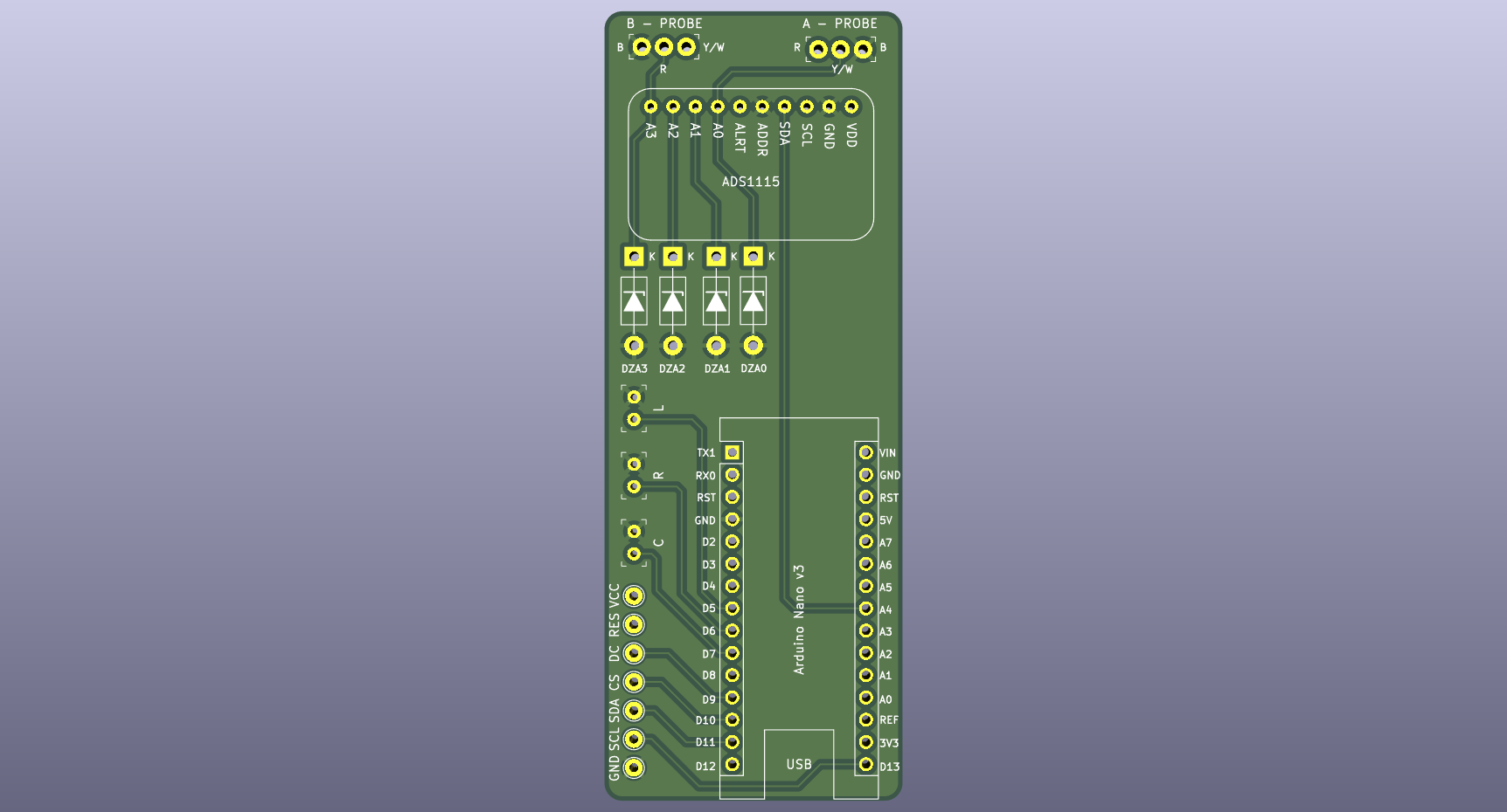
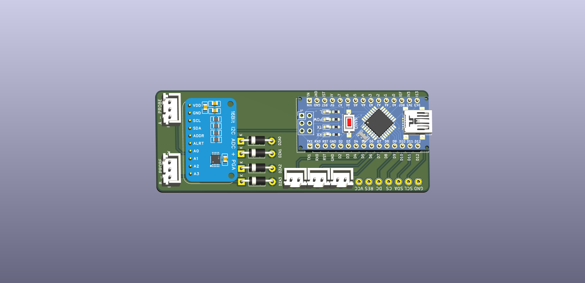
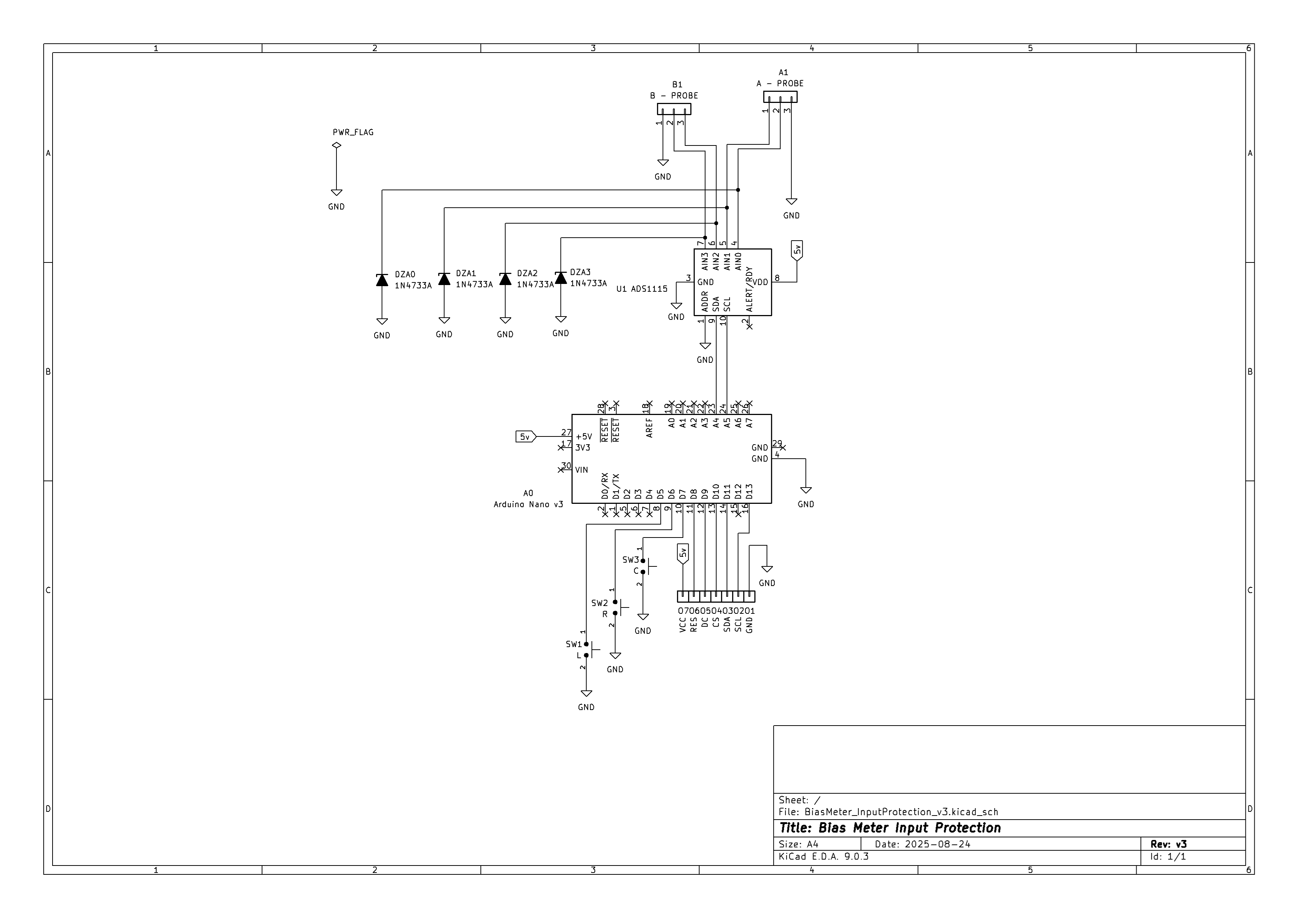
📥 Get KiCad Software: Download Official KiCad
| Component | Pin Name | Nano Pin |
|---|---|---|
| Buttons | Left Button | D5 |
| Right Button | D6 | |
| Select/Center | D7 | |
| Display (ST7735) | CS | D10 |
| DC (A0) | D9 | |
| RST | D8 | |
| SDA (MOSI) | D11 | |
| SCK (SCLK) | D13 | |
| ADC (ADS1115) | SDA | A4 |
| SCL | A5 | |
| VCC | 5V | |
| GND | GND |
If you are building your own probes, correct wiring is essential for the math to work.
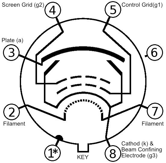
Figure: Standard Octal (8-Pin) Pinout (Bottom View).
Correctly powering the Arduino Nano is critical to prevent damage to your computer, the BiasPro, or the amplifier.
The safest way to power this device during use is with a dedicated USB wall charger (like a standard phone charger).
Specs: 5V Output, at least 500mA (0.5A).
Connector: Mini-USB or USB-C (for Nano).
⚠️ IMPORTANT - 2-Prong Only: You must use a charger that has only 2 prongs (ungrounded).
You can power the Arduino Nano via the VIN and GND pins using a 9V battery.
DO NOT power the BiasPro from your computer's USB port while it is connected to an amplifier.
The Danger: Desktop computers (and many laptops) are grounded. Connecting the USB cable ties the Arduino's Ground to the Computer's Earth Ground. Since the Probe's Ground is connected to the Amp's Ground, you create a direct Ground Loop.
Risk: If a probe accident occurs or there is a voltage potential difference, high current could flow through the USB cable, destroying your computer's motherboard, the Arduino, or the amplifier.
Uploads: It is safe to connect to the computer to upload code ONLY IF the bias probes are disconnected from the amplifier.
Debugging: You can use the Arduino IDE Serial Monitor (9600 baud) to confirm the firmware boots (it prints a BiasPro Booting... status message), but ensure the probes are NOT connected to a live amplifier. If you must debug a live circuit, you must use a USB Isolator to protect your equipment.
Library Dependencies: Install the following via the Arduino IDE Library Manager:
Adafruit GFX LibraryAdafruit ST7735 and ST7789 LibraryAdafruit BusIOHardware Setup:
Upload: Flash the BiasPro firmware to your Arduino Nano.
"RAW SENSORS" is a highly visible, dedicated diagnostics menu item located at the very end of the Tube Profile Selection carousel. It is accessed and exited using a standard short click of the center button. Selecting this profile enters a diagnostics mode that displays the raw telemetry data coming directly from the Analog-to-Digital Converter (ADC) before final mathematical conversions are applied.
Raw ADC Counts (e.g., CATH: 5254): These are the unconverted digital integer values read directly from the ADS1115 chip. The chip measures the physical voltage and outputs a proportional number ranging from -32768 to +32767.
Millivolts (e.g., 41.04mV): The system mathematically converts the raw integer count into actual millivolts (mV).
This screen is highly useful for troubleshooting probe connections, checking for ADC noise, or manually verifying the calibration math.
1. The "Invisible Spaces" in the Profile Editor
When creating a new tube profile, the Name field holds exactly 6 characters. If you type a short name like 6V6 (3 characters), you still have 3 invisible blank spaces remaining.
The Quirk: The system will not drop down to the "Max Watts" line until you clear all 6 slots.
The Solution: Simply rapid-click the Center button 3 times to skip past the invisible empty spaces and move to the next line.
2. Screen Grid Current (Src) is in Permille (/1000)
To calculate True Plate Dissipation, the BiasPro subtracts the Screen Grid Current from the Cathode reading. Floating-point decimals (like 5.5%) crash the Arduino's memory limit. Therefore, the firmware uses Permille (parts-per-thousand).
55 /1000130 /100040 /1000Bench Setup: Connect your amplifier to a speaker load or reactive load box. An Isolation Transformer and a Variac are highly recommended for stable wall-voltage readings.
Probe Connection: Ensure the amplifier is powered OFF. Remove the power tubes, insert the BiasPro probes into the amp sockets, and place the tubes into the top of the probes.
Select Tube Profile: Power on the BiasPro. Select the matching tube profile (e.g., 6L6GC). Press Center to enter Live Bias Mode.
Power the Amp: Turn the amplifier ON. Wait for the tubes to warm up, then disengage standby.
Adjust Bias: Watch the % and Watts readings. Adjust your amplifier's internal bias potentiometer until the hottest tube reaches your desired target:
HARDWARE FAULT: CHECK I2C: The ADS1115 ADC has disconnected. The meter will permanently halt to prevent phantom voltage readings. Power cycle to reset.
VOLTAGE LOCKOUT: If the probes detect a voltage spike above your configured safety limit (default 600V), the screen turns red and locks. You must wait for the voltage to drop at least 50V below the limit before the meter releases the lock. Do not attempt to bypass this.
The Tube Profile Manager is powerful because it allows you to customize how the meter calculates Bias for specific tube types.
This determines the "Red Line" for your tube. The meter uses this value to calculate the % Dissipation displayed on the screen.
How to set: Look up the "Max Plate Dissipation" in the tube's datasheet.
Examples (Typical Values):
Usage: If you set this to 25W and measure 17.5W of dissipation, the meter will display 70%.
True Plate Current = Measured Current - (Measured Current * ScreenFactor)The meter comes with Default calibration settings (Automatic), but for professional accuracy, we strongly recommend Manual calibration.
How to Enter Calibration Mode:
To prevent entering invalid or dangerous values, the firmware enforces strict calibration bounds and adjustment steps:
Scale A / Scale B): Range is 5.00 to 20.00 (adjusted in steps of 0.05 via Left/Right).Shunt A / Shunt B): Range is 500mR to 5000mR (representing 0.50Ω to 5.00Ω, adjusted in steps of 10mR). The software displays and stores this in milliohms (mR) to maintain high precision without the memory overhead of floating-point decimals.Limit): Range is 300V to 800V (adjusted in steps of 5V).When you first power on the device (or after a reset), it loads standard default values:
Use Case: This is "Plug and Play." It works reasonably well for standard probes, but real-world resistors often vary slightly. It is always good practice to check these settings against a multimeter anyway.
For the highest accuracy, use this method to match the meter readings to a trusted Digital Multimeter (DMM).
[!WARNING] The over-voltage LOCKOUT alarm does not run on the Calibration screen. The automatic red-screen lockout is active only in Live Bias mode. During voltage-scale calibration the amp is energised and this screen shows a live "Live V" reading, but it will not trip the lockout if the amp faults high. Treat "Live V" as a readout only — not a safety alarm. Watch your DMM, keep the plate voltage within your amp's expected range, and if anything looks wrong, shut down at the amp. Once calibrated, do your actual biasing from Live Bias mode, where the lockout is active.
If you are using commercial probes like the Tube Depot Bias Scout, they typically have three banana plugs: Red, Black, and White.
1.2Ω (Total) - 0.1Ω (Leads) = 1.1Ω (True Resistance)1.1Ω × 1000 = 1100mRThe "Limit" setting is a safety tripwire.
Your settings are written to EEPROM automatically — each time you press Center to advance to the next field, and again whenever you leave the screen. There is no separate "save" item to look for. To leave calibration:
Either exit stores your latest values, so you can leave whichever way is convenient.
If you are building this on perfboard (instead of using the custom PCB), we strongly recommend adding input protection to save your Arduino in case of a catastrophic tube failure.
Yes. BiasPro v1.1.1 achieves and delivers this four-digit precision across all metrics (0.1V resolution for plate voltage and 0.1mA for cathode current) through two key engineering upgrades:
High-Precision 16-Bit Telemetry: Bypassing the stock 10-bit Arduino ADC in favor of an ADS1115 ADC managed directly via targeted I2C register commands allows for granular data capture down to a tiny 0.0078125 mV per bit.
Empirical Software Calibration: By taking measurements with a high-quality multimeter (such as a Fluke 115) and factoring out multimeter lead resistance, you can enter custom milliohm (mR) shunt values and scale factors directly into the on-board EEPROM menu. This process empirically matches the math engine to the unique physical tolerances of your probes.
Yes, explicitly and dynamically. The BiasPro is a continuous monitor designed for active bench analysis, rather than a device that merely captures a snapshot.
Thermal Drift Monitoring: While running in Live Bias mode, the system continuously polls the ADC channels several times per second, maintaining steady readouts through flicker-free incremental redraws. This feature allows technicians to let the amplifier idle and track current drift over extended one-hour burn-in windows.
Active Safety Catching: If a power tube encounters a severe failure such as thermal runaway or a structural grid short, the plate voltage or current will drift uncontrollably. BiasPro actively monitors this loop on every cycle and will instantly trip the red VOLTAGE LOCKOUT emergency screen to secure the workbench.
BiasPro is an independent clean-room rewrite of the earlier ToneAlchemy BiasMeter project. The BiasPro firmware was re-architected and rewritten without intentionally reusing source code from the earlier implementations.
The broader project lineage includes:
The earlier projects were distributed under CC BY 4.0 and are acknowledged here for their historical contribution to the development of the Arduino tube-bias-meter concept.
This project is released under the MIT License. See LICENSE for details. Third-party libraries and components remain subject to their respective licences.
| Qty | Value | Footprint | References |
|---|---|---|---|
| 4 | 1N4733A | PCM_Diode_THT_AKL:D_DO-41_SOD81_P10.16mm_Horizontal_Zener | DZA0, DZA1, DZA2, DZA3 |
| 1 | A - PROBE | Source_Footprints:PinHeader_1x3_P2.54_Drill1.1mm | A1 |
| 1 | ADS1115 | Adafruit_ADS1115:Adafruit_ADS1115_NEW | U1 |
| 1 | Arduino Nano v3 | Module:Arduino_Nano | A0 |
| 1 | B - PROBE | Source_Footprints:PinHeader_1x3_P2.54_Drill1.1mm | B1 |
| 1 | C | Source_Footprints:PinHeader_1x2_P2.54mm | SW3 |
| 1 | CS | TestPoint:TestPoint_THTPad_D2.0mm_Drill1.0mm | O4 |
| 1 | DC | TestPoint:TestPoint_THTPad_D2.0mm_Drill1.0mm | O5 |
| 1 | GND | TestPoint:TestPoint_THTPad_D2.0mm_Drill1.0mm | O1 |
| 1 | L | Source_Footprints:PinHeader_1x2_P2.54mm | SW1 |
| 1 | R | Source_Footprints:PinHeader_1x2_P2.54mm | SW2 |
| 1 | RES | TestPoint:TestPoint_THTPad_D2.0mm_Drill1.0mm | O6 |
| 1 | SCL | TestPoint:TestPoint_THTPad_D2.0mm_Drill1.0mm | O2 |
| 1 | SDA | TestPoint:TestPoint_THTPad_D2.0mm_Drill1.0mm | O3 |
| 1 | VCC | TestPoint:TestPoint_THTPad_D2.0mm_Drill1.0mm | O7 |
It measures 33.9 × 90 mm and has 2 copper layers, 1.6 mm thick.
18 parts, built around the ADS1115 and 1N4733A. The full list of its parts is on this page, with links to each part's symbol and footprint where PCBKit's library has them.
From the ToneAlchemy/BiasPro repository on GitHub, at the commit this page was made from: the board is HARDWARE - PCB KICAD/BiasPro - KICAD/Kicad - Bias_Meter - Project Files/BiasPro_InputProtection_v3.kicad_pcb and its schematic HARDWARE - PCB KICAD/BiasPro - KICAD/Kicad - Bias_Meter - Project Files/BiasPro_InputProtection_v3.kicad_sch. PCBKit opens the board in the browser, with nothing to install.
Its repository publishes it under the MIT licence: you may reuse it on that licence's terms (keep the author's notice, and for a copyleft licence share your changes alike).
profdc9/DRSSTC-PCB-Pack
A pack of PCBs for a dual resonant solid state tesla coil setup. Pretty much everything you need.


robsonsmartins/usbflashprog
A memory device programmer (Flash/EPROM/E2PROM) board and software, connected to PC by USB port.


profdc9/LinearPS
Linear constant constant/current constant voltage power supply PCB

Starsurfer78/TeensyMower-PCBs
PCB's Folder for Teensy 4.1 based Robot Lawn Mower

