2 layers28 × 51 mm

 tokai-student-rocket-project/Pcb-Name-Card-R4
Renesas RA4M1 (Arduino UNO R4) を搭載した名刺サイズの自作マイコン基板。USB Type-C・CAN通信 (TJA1051T/3)・NeoPixel・各種I/Oヘッダーを備えた実用的なPCB名刺のKiCad設計データです。
Pcb Name Card R4 is an open-source printed circuit board by tokai-student-rocket-project, from the tokai-student-rocket-project/Pcb-Name-Card-R4 repository on GitHub. It is a 2-layer board of 91 × 55 mm with 49 parts on 72 nets, routed with 571 tracks and 363 vias.
It is built around the TJA1051T/3/1, MF-NSMF050-2 and RB160M-30TR, with the SKRPACE010 and WS2812B among its other parts. Its parts include 13 resistors, 10 capacitors, 8 connectors, 6 diodes and 3 switches. It belongs with the lEDs and displays boards of this library.


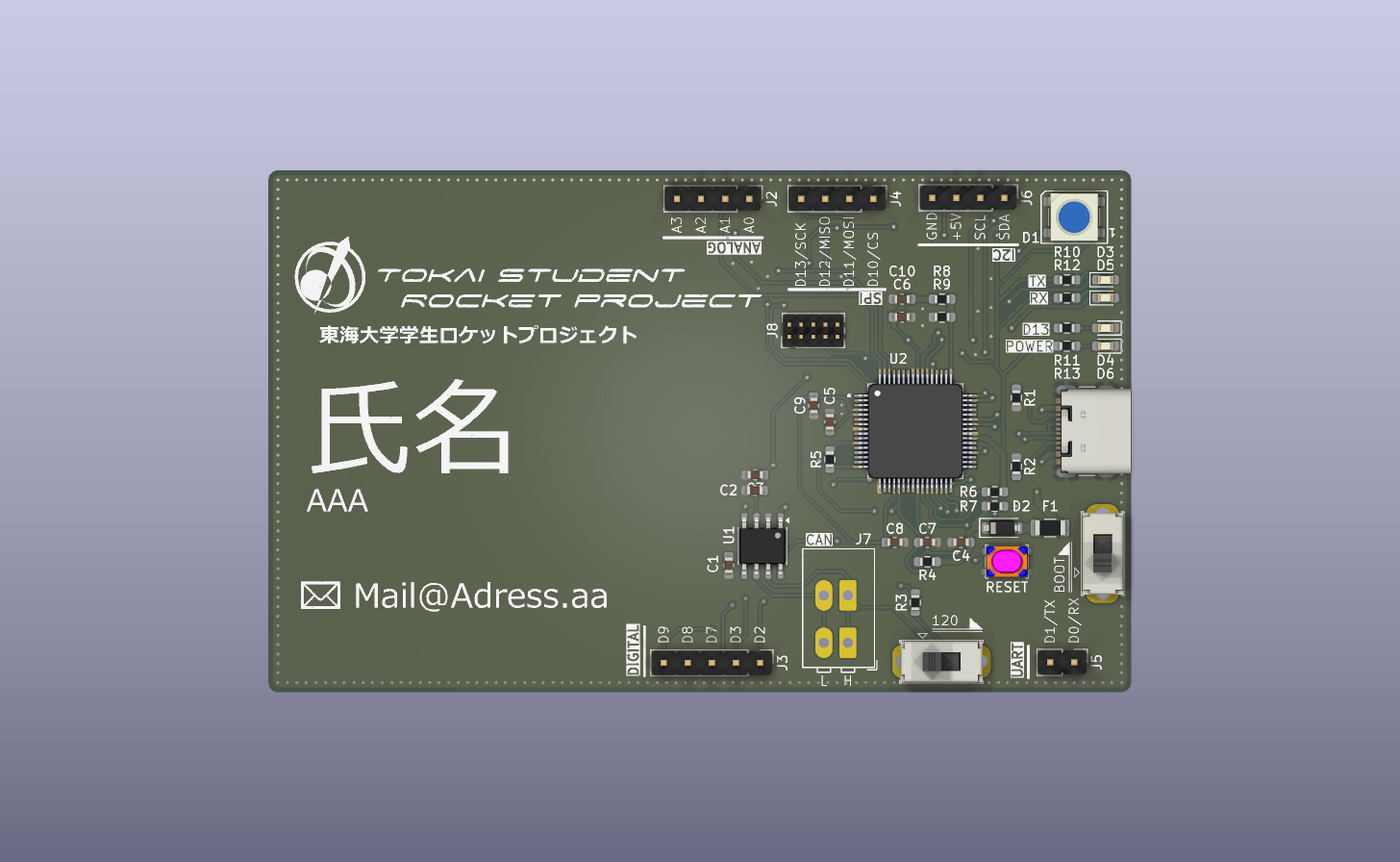
KiCad で設計した Arduino UNO R4 (Renesas RA4M1) ベースの名刺サイズ基板(PCB Name Card)です。
名刺としてのデザイン性を備えつつ、USB Type-C、CAN通信機能、NeoPixel制御、各種標準インターフェース(UART / SPI / I2C / Analog)を搭載した実用的なマイコンボードとして動作します。
R7FA4M1AB3CFM) を搭載(Arm Cortex-M4F 48MHz, 256KB Flash, 32KB SRAM)。| 項目 | 仕様 |
|---|---|
| メインMCU | Renesas RA4M1 (R7FA4M1AB3CFM / LQFP-64) |
| 動作周波数 | 48 MHz (Arm Cortex-M4F) |
| メモリ | Flash 256 KB / SRAM 32 KB / Data Flash 8 KB |
| 動作電圧 | 5V |
| 電源供給 | USB Type-C (5V) |
| USB コネクタ | USB Type-C |
| CAN トランシーバ | NXP TJA1051T/3 (SOIC-8, 120Ω 終端抵抗実装) |
| デバッグ端子 | 10ピン SWD (1.27mm pitch) |
| 基板外形 | 名刺サイズ |
| ピン番号 | ピン名 | 主な機能 / 接続先 | 備考 |
|---|---|---|---|
| D0 | RX | UART / RX | シリアル受信ヘッダー (J5) |
| D1 | TX | UART / TX | シリアル送信ヘッダー (J5) |
| D2 | NeoPixel | NeoPixel (WS2812B / SK6812) 制御信号 | フルカラーLED用 |
| D3 | GPIO | 汎用 GPIO | - |
| D4 | CAN TX | CAN / TX | TJA1051T/3 CAN送信 |
| D5 | CAN RX | CAN / RX | TJA1051T/3 CAN受信 |
| D6 | CAN Silent | CAN Silent Mode 制御 | LOW: 通常動作 / HIGH: サイレントモード |
| D7 | GPIO | 汎用 GPIO | - |
| D8 | GPIO | 汎用 GPIO | - |
| D9 | GPIO | 汎用 GPIO | - |
| D10 | SPI CS | SPI / CS | SPI ヘッダー (J4) |
| D11 | SPI MOSI | SPI / MOSI | SPI ヘッダー (J4) |
| D12 | SPI MISO | SPI / MISO | SPI ヘッダー (J4) |
| D13 | LED / SCK | オンボードLED / SPI SCK | SPI ヘッダー (J4) 兼 インジケータLED |
| A0 | Analog 0 | アナログ入力 0 / GPIO | アナログヘッダー (J2) |
| A1 | Analog 1 | アナログ入力 1 / GPIO | アナログヘッダー (J2) |
| A2 | Analog 2 | アナログ入力 2 / GPIO | アナログヘッダー (J2) |
| A3 | Analog 3 | アナログ入力 3 / GPIO | アナログヘッダー (J2) |
| A4 | SDA | I2C / SDA | I2C データライン |
| A5 | SCL | I2C / SCL | I2C クロックライン |
.
├── KiCad/
│   └── Pcb-Name-Card-R4/
│       ├── Pcb-Name-Card-R4.kicad_sch  # KiCad 回路図データ
│       ├── Pcb-Name-Card-R4.kicad_pcb  # KiCad PCBレイアウトデータ
│       ├── Pcb-Name-Card-R4.kicad_pro  # KiCad プロジェクトファイル
│       ├── Pcb-Name-Card-R4.xlsx       # 部品表 (BOM)
│       └── production/                 # 製造用 Gerber / Drill データ
├── Pcb-Name-Card-R4.png                # 基板外観イメージ画像
├── PcbNameCardR4.step                  # 3D STEP モデルデータ
└── README.md # 本ドキュメント| Qty | Value | Footprint | References |
|---|---|---|---|
| 6 | LOGO | LOGO | G***, G***, G***, G***, G***, G*** |
| 5 | 0.1u | Capacitor_SMD:C_0603_1608Metric_Pad1.08x0.95mm_HandSolder | C1, C2, C6, C9, C10 |
| 4 | 5.1k | Resistor_SMD:R_0603_1608Metric_Pad0.98x0.95mm_HandSolder | R4, R5, R6, R7 |
| 3 | 10k | Resistor_SMD:R_0603_1608Metric_Pad0.98x0.95mm_HandSolder | R10, R11, R12 |
| 2 | 4.7u | Capacitor_SMD:C_0603_1608Metric_Pad1.08x0.95mm_HandSolder | C7, C8 |
| 2 | 5.1kR | Resistor_SMD:R_0603_1608Metric_Pad0.98x0.95mm_HandSolder | R1, R2 |
| 2 | Green | LED_SMD:LED_0603_1608Metric_Pad1.05x0.95mm_HandSolder | D3, D5 |
| 2 | Orange | LED_SMD:LED_0603_1608Metric_Pad1.05x0.95mm_HandSolder | D4, D6 |
| 1 | 0.1uF | Capacitor_SMD:C_0603_1608Metric_Pad1.08x0.95mm_HandSolder | C4 |
| 1 | 100k 0.1% | Resistor_SMD:R_0603_1608Metric_Pad0.98x0.95mm_HandSolder | R8 |
| 1 | 120 | Resistor_SMD:R_0603_1608Metric_Pad0.98x0.95mm_HandSolder | R3 |
| 1 | 13.7k 0.1% | Resistor_SMD:R_0603_1608Metric_Pad0.98x0.95mm_HandSolder | R9 |
| 1 | 1u | Capacitor_SMD:C_0603_1608Metric_Pad1.08x0.95mm_HandSolder | C5 |
| 1 | 20k | Resistor_SMD:R_0603_1608Metric_Pad0.98x0.95mm_HandSolder | R13 |
| 1 | 22u | Capacitor_SMD:C_0603_1608Metric_Pad1.08x0.95mm_HandSolder | C3 |
| 1 | Analog | Connector_PinHeader_2.54mm:PinHeader_1x04_P2.54mm_Vertical | J2 |
| 1 | BOOT | Button_Switch_THT:SW_Slide_SPDT_Straight_CK_OS102011MS2Q | SW3 |
| 1 | CAN | TerminalBlock_WAGO:TerminalBlock_WAGO_233-502_2x02_P2.54mm | J7 |
| 1 | Digital | Connector_PinHeader_2.54mm:PinHeader_1x05_P2.54mm_Vertical | J3 |
| 1 | I2C | Connector_PinHeader_2.54mm:PinHeader_1x04_P2.54mm_Vertical | J6 |
| 1 | MF-NSMF050-2 | Fuse:Fuse_1206_3216Metric | F1 |
| 1 | R7FA4M1AB3CFM_AA0 | TSRP_Arduino:QFP50P1200X1200X170-64N | U2 |
| 1 | RB160M-30TR | Diode_SMD:D_SOD-123 | D2 |
| 1 | SKRPACE010 | TSRP_Button_Switch_SMD:SKRPACE010 | SW2 |
| 1 | SPI | Connector_PinHeader_2.54mm:PinHeader_1x04_P2.54mm_Vertical | J4 |
| 1 | SWD | Connector_PinHeader_1.27mm:PinHeader_2x05_P1.27mm_Vertical | J8 |
| 1 | TJA1051T-3 | Package_SO:SOIC-8_3.9x4.9mm_P1.27mm | U1 |
| 1 | TerminalResistor | Button_Switch_THT:SW_Slide_SPDT_Straight_CK_OS102011MS2Q | SW1 |
| 1 | UART | Connector_PinHeader_2.54mm:PinHeader_1x02_P2.54mm_Vertical | J5 |
| 1 | USB_C_Receptacle_USB2.0_14P | Connector_USB:USB_C_Receptacle_GCT_USB4105-xx-A_16P_TopMnt_Horizontal | J1 |
| 1 | WS2812B | LED_SMD:LED_WS2812B_PLCC4_5.0x5.0mm_P3.2mm | D1 |

punkfab/pcb-corpus
235 real KiCad boards from open-source hardware repositories, prepared as a placement and routing benchmark


tokai-student-rocket-project/H-62-Avionics
H-62搭載計器 すばる1.3 | 2025年度 夏季 能代 NOGO


garypippi/pippitank
R1 = 67kΩ (47kΩ + 20kΩ) R2 = 10kΩ (8.4V時 1.091V、6.0V時 0.779V)


Liesegang/env_sensor
Outdoorの開発・検証はファームウェア、 Web受信アプリ、BLE仕様を参照。 Card firmwareはv2基板で毎分測定・BLE送信、 10分ごとのSD一括記録、1時間ごとの電子ペーパー更新を行う。 iPhoneアプリは共通BLEで受信し、バックグラウンド収集・端末内の履歴保存・JSON / CSV書き出しを行う。 資料の一覧はデータシートにある。
It measures 91 × 55 mm and has 2 copper layers, 1.6 mm thick.
49 parts, built around the TJA1051T/3/1, MF-NSMF050-2, RB160M-30TR and SKRPACE010. The full list of its parts is on this page, with links to each part's symbol and footprint where PCBKit's library has them.
From the tokai-student-rocket-project/Pcb-Name-Card-R4 repository on GitHub, at the commit this page was made from: the board is KiCad/Pcb-Name-Card-R4/Pcb-Name-Card-R4.kicad_pcb and its schematic KiCad/Pcb-Name-Card-R4/Pcb-Name-Card-R4.kicad_sch. PCBKit opens the board in the browser, with nothing to install.
Its repository states no licence, so its author keeps all rights: ask tokai-student-rocket-project before reusing the design.